3.2 Pipeline
A switch pipeline resembles pipelined execution in a vector processor: a single packet header indicates how to process all of the internal datapath transfer units of a packet. Packets at different input ports are independent and are handled in parallel, similarly to multiple independent instruction streams. Pipeline latency may be several cycles; line-rate stages are instead defined by an initiation interval of one cycle whenever their downstream resource is ready.
The central challenge in PRISM is to sustain line-rate operation while safely coordinating forwarding and local collective processing. The pipeline must:
- resolve resource contention;
- prevent structural and data hazards;
- preserve packet ordering where required;
- propagate backpressure without corrupting state or creating deadlock.
These requirements become critical when forwarded and generated traffic converge on shared arbitration, crossbar, and egress resources.
This section first introduces a conventional cut-through switch pipeline as a reference model. It then extends that model to the final PRISM switch architecture. The last section separately describes the collective-node RTL implemented today.
Target architecture and current RTL
The current RTL implements the collective path, not transparent forwarding, VOQs, received RES/PROGRESS, replay, or the general crossbar.
3.2.1 Basic Pipeline
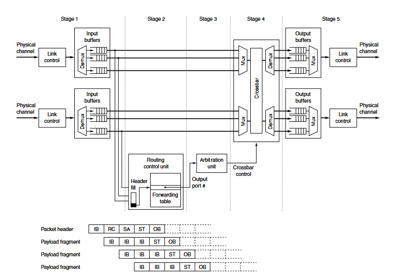
Consider a conventional cut-through switch in which a forwarding table selects the egress. The first stage (after first buffering) parses the header and extracts the destination and other routing fields.
The second stage queries the forwarding table. Meanwhile, the remaining packet beats continue to arrive and wait in the ingress queue.
In the third stage, the packet participates in arbitration for access to the selected output port. Once the request is granted, the fourth stage configures the crossbar to establish a temporary connection between the corresponding ingress and egress ports. In the fifth stage, the packet header reaches the output-side buffer and becomes available for transmission over the external link.
Only the header traverses forwarding lookup and arbitration because those stages establish the internal route. After the crossbar connection is configured, the payload and trailer bypass the control-processing stages.
They traverse only ingress buffering, crossbar transfer, and egress buffering or transmission. This is the five-stage organization illustrated in Figure F.26 of Hennessy and Patterson.[^switch-pipeline]
3.2.2 Introducing Virtual Output Queues
A virtual-channel switch may add virtual-channel allocation and arbitrate every beat. The final PRISM switch instead schedules packets over Virtual Output Queues (VOQs).
Route and queue selection occur once per packet. A successful crossbar grant remains locked until the accepted TLAST, although complex routing and arbitration may still require several registered cycles.
Why Virtual Output Queues?
VOQs separate packets by destination egress, preventing a blocked output from delaying traffic destined for available ports. They also provide a clean, scalable interface through which forwarded and PRISM-injected packets can share the same buffering and scheduling infrastructure while remaining independently arbitrated.
With N physical ingress ports, the forwarding side exposes VOQ[I][O] for every ingress I and egress O. Generated PRISM traffic adds internal K source rows but uses the same per-egress arbitration.
The matrix is write-parallel by source row. Each row has its own enqueue path, so all physical ingress and internal injection sources may write one beat in the same cycle, including when several choose the same egress: those writes land in different VOQ[source][egress] cells. Contention occurs later at the egress-column arbiter.
3.2.99 Current implemented collective node
The sections above define the integration target. The RTL in repo/prism-hdl/rtl.f currently implements the following bounded subset.
External boundary
The reusable core exposes NUM_PORTS independent AXI4-Stream RX/TX pairs. The default profile uses two ports, 512 data bits, 64 tkeep bits, tlast, one tuser bit, and a 250 MHz target clock. A transfer occurs only on tvalid && tready; all data and sideband signals remain stable while stalled.
At 512 bits and 250 MHz the interface capacity is 128 Gbit/s per port and per direction. This value is not a claim of usable payload throughput or physical timing closure.
Ingress and classification
Each port instantiates:
prism_axis_frame_fifo, which stores beats in synchronous block RAM, validatestkeep, counts bytes, and makes only complete frames visible;prism_header_parser, which extracts the 40-byte fixed prefix from the first beat in network byte order;prism_packet_validator, which checks adapter/keep errors, EtherType, local MAC, version, opcode, flags, operation/contributor lookup, payload length, andLAST_CHUNK;prism_ingress_demux, which locks one frame to CONTROL, DATA, or drain/drop until the acceptedtlast.
This is store-and-forward admission. A malformed frame cannot update control or arithmetic state. The current demultiplexer has no transparent forwarding path. Received RES and PROGRESS are not handled by the current RTL.
The frame memory uses a one-cycle synchronous read request and a four-entry elastic response queue. Prefetch sustains one beat per cycle, while the request counter prevents reads from entering an incomplete frame.
Parsing, the shared lookup, geometry derivation, and final validation are split by registers. With an immediate lookup grant, the sequence takes three cycles from parsed-header capture to the validated descriptor; arbitration can add more. The operation lookup starts from the parsed header. Its registered group slot then addresses the contributor table, so interleaved ports cannot combine table responses from different operations. Starting the lookup early hides the two registered geometry stages and preserves the frame interval.
CONTROL path
flowchart LR
  C0["Per-port CONTROL frame"] --> CD["depacketizer"]
  CD --> FA["fragment arbiter"]
  FA --> RA["reassembler"]
  RA --> TD["TLV decoder"]
  TD --> ST["stager"]
  ST --> EX["executor"]
  EX --> TB["session / group / operation tables"]
  EX --> RE["response encoder"]
  RE --> CP["CONTROL packetizer"]
The depacketizer serializes the payload as bytes. The arbiter owns one complete fragment at a time. The reassembler accepts a bounded number of fragmented transactions, keyed by cookie/transaction/command, and publishes only a complete message. The TLV decoder emits structural events; the stager converts valid records into one typed request. State changes occur only in the owning session, group, or operation table after full staging. OP_PREPARE adds one registered route-geometry stage before the operation-table update; this is a control-plane latency and does not change arithmetic throughput.
The response encoder builds the selected TLVs in network byte order. The packetizer captures the response payload before transmitting a complete Ethernet CONTROL frame on the request's ingress port. Payload bytes are packed into beat-aligned synchronous RAM; a prefetch cycle after capture keeps the 512-bit transmit path free of an asynchronous 64-read-port mux. The synthesis tool selects the physical memory primitive.
DATA and arithmetic path
flowchart LR
  D0["Per-port DATA frame"] --> DP["depacketizer"]
  DP --> FQ["per-port issue-group FIFO"]
  FQ --> BS["operation/range issue-bank selection"]
  BS --> EB["2-stage elastic bank boundary"]
  EB --> BA["4 shared issue slices per bank"]
  BA --> RA["reduced-group arbiter"]
  RA --> OC["result conversion"]
  OC --> CS["chunk store"]
prism_data_depacketizer removes the 40-byte Ethernet/PRISM prefix and emits compact 512-bit wire-format issue groups with metadata. A three-beat reservoir bridges the unaligned 40-byte prefix without fragmenting later full-width groups. A tile always contains up to TILE_ELEMENTS=16 elements. One issue group contains one FP32 tile, two FP16/BF16 tiles, or four INT8 tiles. Each port has an independent work FIFO.
The core keeps this compact payload through the per-port FIFO and hashes each operation/group position over NUM_PORTS issue banks. The selected bank expands the payload into 32-bit arithmetic lanes locally. Different banks can accept work from different ingress ports in the same cycle. After each bank arbiter, two registered elastic stages isolate the selected tile and its ready path from the arithmetic backend. They add two cycles of latency while retaining one accepted tile per cycle and bounded backpressure. prism_issue_backend splits each group across independent sixteen-lane issue slices, converts and reduces every active tile, then rejoins the completed tiles. A two-entry queue in front of every active slice and an acceptance scoreboard preserve the atomic external group handshake. Ready slices enqueue once even if another active slice stalls, so local write enables do not form a cross-slice ready path. Each default bank contains four shared slices; every slice executes the binary32 or the KULISCH_ACC_W-bit Kulisch path selected by operation metadata (279 bits by default). The two-port profile therefore instantiates two arithmetic banks, not separate per-profile banks. A final arbiter merges completed groups into shared result conversion and storage. The chunk store restores monotonically increasing chunk order before routing because independent banks can complete out of order.
The input conversion stage owns datatype conversion. For FP32_ARRIVAL and FP32_ORDERED it produces binary32 lanes. For KULISCH_FP32 it produces KULISCH_ACC_W-bit aligned signed deposits and separate zero/NaN/infinity/overflow flags. A two-stage elastic pipeline separates format decoding, fixed-point alignment, and deposit generation. Metadata and both numeric representations remain aligned while the stage accepts one tile per cycle.
The range scheduler owns contributor masks and numeric state. It reserves a range on the compact input and carries the reservation through local conversion, so wide deposits never wait in a scheduler-entry FIFO. Its key includes the operation and global element range. It rejects a contributor already present in the range, applies FP32_ARRIVAL in accepted order, folds FP32_ORDERED in ascending Contributor ID order, or streams Kulisch deposits. For the current two-contributor FP32_ORDERED profile it sends the ordered pair directly to the sixteen-lane FP32 slice when the second tile arrives. It publishes an output only after all expected contributors have arrived.
Result storage, routing, and egress
The result conversion stage narrows/canonicalizes the final FP32 lanes to the configured output format and preserves the accumulation warning. A one-entry elastic input stage separates completed-group selection from the parallel format converters; it adds one cycle while retaining an II of one. The result chunk store assembles tiles into immutable chunk slots. A reference count keeps one payload alive while the result router enumerates bounded route and replication entries.
Each egress has a prism_result_packetizer. It reads a chunk slot and creates a RES frame with exact tkeep/tlast. A two-source frame arbiter selects CONTROL or RES and locks that selection through the accepted final beat. A final frame FIFO isolates downstream stalls.
Backpressure invariants
- State and indexes advance only on an accepted ready/valid transfer.
- A stalled producer keeps payload and metadata stable.
- A frame arbiter never interleaves two packets.
- A full FIFO propagates
ready=0; it does not silently discard data. - Contributor state changes only after complete frame validation.
- A completed result slot is not released until every armed packet job reports completion.
- Reset clears valid/FSM/ownership state and prevents partial output frames.
Implemented and excluded behavior
| Behavior | Current state |
|---|---|
| In-band CONTROL, sessions, groups, operations | Implemented and exercised by full integration |
REDUCE/ALLREDUCE SUM in a two-port SINGLE node | Implemented and exercised |
| FP32_ARRIVAL, FP32_ORDERED, local Kulisch accumulation | Implemented; focused arithmetic test |
| INT8/FP16/BF16/FP32 input conversion | Implemented at converter boundary |
| FP16/BF16/FP32 result conversion | Implemented; narrower end-to-end coverage |
| Switch-to-switch partial DATA | Protocol field/model only; no multi-switch RTL path |
| PROGRESS, ACK/replay/retry engine | Documented and modeled in the CCL, not in RTL |
| Transparent L2 forwarding, VOQ, general crossbar, shared packet store | Deliberately excluded |
| 250 MHz timing closure | Requires Vivado implementation evidence; not established by simulation |
Measured simulation rates and latencies
At the 250 MHz target clock, the issue-group test sustains one full 512-bit numeric payload beat per cycle. It measures 128 Gbit/s for INT8, FP16, BF16, and FP32 through the shared arithmetic banks for both FP32 and Kulisch accumulation modes. FP32 result narrowing keeps all 64 result lanes parallel. Its FP16 subnormal rounder operates on the 24 significant bits with a bounded shift; it does not instantiate a general 64-bit shifter or serialize result lanes. The sixteen-lane, single-contributor Kulisch microbenchmark measures a 17-cycle, 68 ns fill latency followed by one tile per cycle. The added pipeline depth changes latency, not the initiation interval.
The complete two-rank, two-port REDUCE test uses four 1472-byte result chunks and no artificial egress stalls. It measures 23 consecutive full result tiles at one tile per cycle, 101.66 Gbit/s of result payload at the AXI egress, and 480 ns from the first accepted contribution beat to the first accepted result beat. A SESSION_OPEN request takes 716 ns to the first response beat in the same no-stall simulation.
These are RTL simulation measurements at an assumed 4 ns clock. They are not post-route timing results. A 100 Gbit/s Ethernet PHY also cannot carry 100 Gbit/s of numeric payload because Ethernet framing consumes part of the wire rate; with 1472-byte PRISM result payloads the idealized share is about 95.8 Gbit/s after Ethernet framing, preamble, and inter-packet gap. Whether line coding is included depends on whether the quoted rate is at the MAC or SerDes boundary.