3.2 Pipeline
A switch pipeline resembles pipelined execution in a vector processor: a single packet header indicates how to process all of the internal datapath transfer units of a packet. Packets at different input ports are independent and are handled in parallel, similarly to multiple independent instruction streams. Pipeline latency may be several cycles; line-rate stages are instead defined by an initiation interval of one cycle whenever their downstream resource is ready.
The central challenge in PRISM is to sustain line-rate operation while safely coordinating forwarding and local collective processing. The pipeline must:
- resolve resource contention;
- prevent structural and data hazards;
- preserve packet ordering where required;
- propagate backpressure without corrupting state or creating deadlock.
These requirements become critical when forwarded and generated traffic converge on shared arbitration, crossbar, and egress resources.
This section first introduces a conventional cut-through switch pipeline as a reference model, then follows the collective-node RTL implemented today. Dashed forwarding resources remain part of the target architecture.
3.2.1 Conventional cut-through pipeline
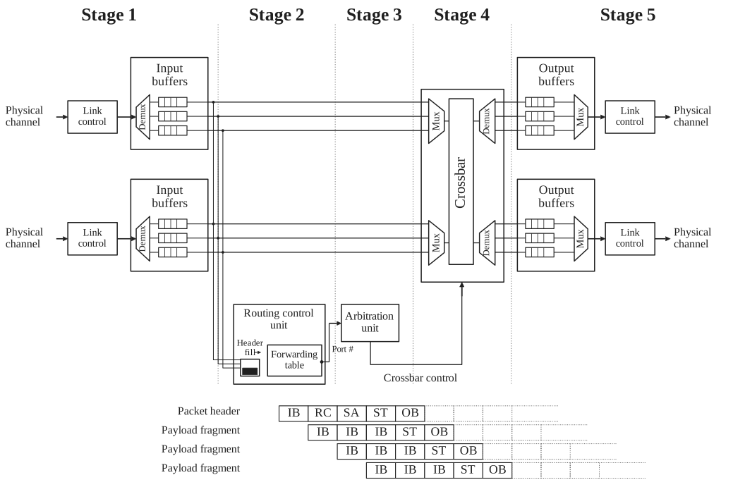
Consider a conventional cut-through switch in which a forwarding table selects the egress. The first stage (after first buffering) parses the header and extracts the destination and other routing fields.
The second stage queries the forwarding table. Meanwhile, the remaining packet beats continue to arrive and wait in the ingress queue.
In the third stage, the packet participates in arbitration for access to the selected output port. Once the request is granted, the fourth stage configures the crossbar to establish a temporary connection between the corresponding ingress and egress ports. In the fifth stage, the packet header reaches the output-side buffer and becomes available for transmission over the external link.
Only the header traverses forwarding lookup and arbitration because those stages establish the internal route. After the crossbar connection is configured, the payload and trailer bypass the control-processing stages.
They traverse only ingress buffering, crossbar transfer, and egress buffering or transmission. The cut-through pipeline figure shows this five-stage organization, redrawn from Hennessy and Patterson.1
3.2.2 PRISM SINGLE pipeline
The conventional forwarding path makes a route decision before letting the packet body cross the switch. PRISM adds a different local destination for DATA: the collective arithmetic engine. The following view tracks one DATA packet through the implemented SINGLE node, rather than depicting a general forwarding fabric.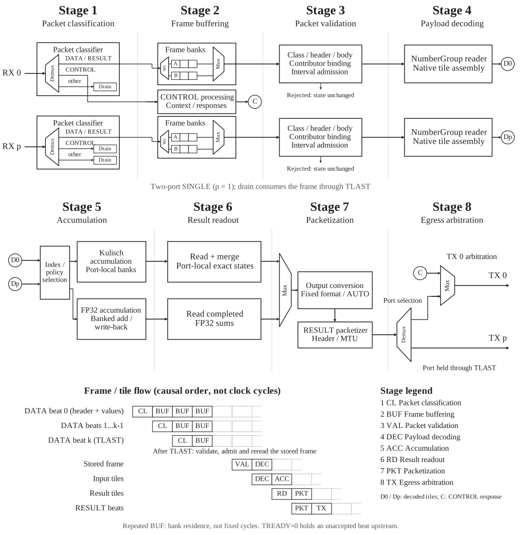
STAGE and COMMIT first install and activate the operation. An accepted DATA frame is classified and stored in a frame bank. After TLAST, the complete frame is validated against that context, admitted, and reread as NumberGroups. The group values become issue groups; their global element indices, not their packet boundaries, select arithmetic lanes. Each contribution updates the selected accumulation policy. The node emits a completed range only after all required contributors for that range have arrived, then selects RESULT formats, forms NumberGroups, and transmits the frame. Thus one DATA packet is not necessarily followed immediately by one RESULT packet.
The PRISM pipeline figure shows eight functional phases. Its lower strip follows input beats, stored frames, and derived tiles in causal order; the cells do not imply a fixed number of clock cycles. Both input ports have a drain path for unsupported traffic. CONTROL processing produces responses that share managed TX port 0 with RESULT frames.
Ready/valid backpressure can pause a stage without losing accepted beats. An initiation interval of one describes steady-state beat acceptance when resources and downstream interfaces are ready; it is not a claim that setup, completion, or a whole collective takes one cycle.
Target architecture and current RTL
The current RTL implements the SINGLE collective path. It does not implement transparent forwarding, VOQs, multi-switch result relay, RESULT acknowledgment/retry, capability query, or the general crossbar.
3.2.3 Architecture views
The current RTL implements one SINGLE collective node. The three views move from frame-class routing to one port's DATA traversal, then open the arithmetic resources. The dashed forwarding branch remains a target; stacked outlines indicate parallel resources, not a fixed number of issue banks.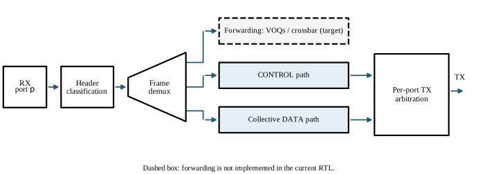
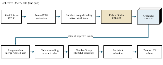
The frame-routing view, collective DATA path, and arithmetic view provide progressively more detail.
DATA and arithmetic paths
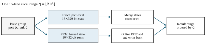
A NumberGroup reader decodes validated DATA into native-width issue groups: 64 INT8, 32 FP16/BF16 or 16 FP32 elements per 512-bit beat. A dispatcher distributes each group across sixteen-lane arithmetic slices. Group boundaries and ingress ports do not determine arithmetic ownership: element index i selects range i // 16 and lane i % 16. Matching positions contribute to the same result.
KULISCH_FIXED uses parallel port-local accumulators of KULISCH_W bits (320 by default, 280 in the U280 build). Their states are merged after all expected contributions and either rounded once to a selected native RESULT format or emitted as exact Kulisch values. FP32_ARRIVAL updates banked FP32 sums as validated tiles are admitted. Each bank reads local state, adds through the pipelined FP32 unit, and writes the rounded sum back. Per-lane reservations prevent read-after-write conflicts; independent positions can enter each cycle. Completed rows are read back through the same memory port. Bank arbitration defines admission order, including simultaneous ports. A striped, bounded store restores vector order and holds the rounded native vector for RESULT delivery. Its maximum logical capacity is 4096 FP32 values (16 KiB); a 512-bit by 256-word implementation may use eight RAMB36 blocks when mapped as 64-bit-wide physical banks. A rounded FP32 tile can also pass through the lossless AUTO classifier after accumulation; eight stored tiles are read together for narrow AUTO RESULT formats. Resource cost depends on mapping and should be taken from implementation reports for the revision being evaluated.
The result sender forms NumberGroup RESULT frames, joins adjacent uniform groups across tile boundaries within each packet, and transmits them to the selected Reduce or AllReduce recipients without RESULT ACK or retry. The current node has no transparent forwarding fabric or integrated tree role; exact partial generation and merge are verified in a separate RTL harness.
John L. Hennessy and David A. Patterson, Computer Architecture: A Quantitative Approach, 5th ed. (Morgan Kaufmann, 2011), Appendix F, Fig. F.26. ↩