Protocol
PRISM is a Layer-2 protocol for FPGA-based System Area Networks (SANs), carrying collective operations directly over Ethernet frames. Its target architecture combines normal forwarding with local collective processing and bounded hop-by-hop reliability. The current RTL implements one SINGLE collective node without forwarding or replay.
The implemented node supports two MPI-style semantics:
REDUCE: several ranks contribute, but one selected rank receives the sum;ALLREDUCE: the same sum is returned to every participating rank.
A rank is one participating process or accelerator endpoint. In a reduction tree, leaf switches receive rank contributions, optional internal switches combine partial sums, and one aggregation root produces the final result.
The packet model has four local classes: in-band CONTROL, contributions and partials in DATA, results in RES, and reliability feedback in PROGRESS. The current node implements CONTROL and endpoint DATA reception plus generated RES; the wider registry is not itself an RTL support claim.
PRISM is a research FPGA datapath, not a complete production Ethernet switch. The protocol therefore prioritizes a clear packet model, reproducible tests, and implementable RTL over a broad management or security stack.
Protocol goal
The first packet beat contains enough information for the parser to select forwarding, CONTROL, DATA, RES, or PROGRESS handling before the numeric payload reaches the collective engine.
This page moves from frame ownership, identity, chunking, and setup to packet layouts. It then shows the implemented single-node flow and the complete multi-switch storyboard before collecting the Protocol 1.0 registries.
Frame ownership and forwarding
PRISM classification proceeds from the outer Ethernet frame inward:
- Parse destination MAC, source MAC, and EtherType.
- If EtherType is not
0x88B5, apply the normal Layer-2 forwarding policy. - If the frame is PRISM but its destination MAC is not local, forward it unchanged when policy permits.
- Decode the PRISM opcode only for a locally addressed PRISM frame.
flowchart LR
    RX["Ethernet frame"] --> ET{"PRISM EtherType?"}
    ET -->|No| L2["Layer-2 forwarding"]
    ET -->|Yes| OWN{"Destination MAC local?"}
    OWN -->|No| L2
    OWN -->|Yes| OP{"Opcode"}
    OP -->|CONTROL| CTRL["Control path"]
    OP -->|COL_DATA| DATA["Collective engine"]
    OP -->|COL_RES| UNSUP["Unsupported receive class"]
    OP -->|COL_PROGRESS| UNSUP
    OP -->|Unknown| BAD["Invalid packet"]
The destination MAC and opcode answer different questions:
- the MAC selects the next node or local owner;
- the opcode selects what that owner does with the packet.
The current collective-node RTL drains both forwarding branches. They remain in the protocol and target architecture so that local collective handling can be integrated into a complete switch without changing the wire model.
Common frame format
The PRISM header is carried directly inside an Ethernet frame. The Ethernet header selects the next destination; the PRISM header identifies the packet class and the collective operation. The normative byte-order rule is stated with the packet layouts below.
For a standard PM_OP_COL_DATA or PM_OP_COL_RES frame, the first 512-bit AXI4-Stream beat is:
%%{init: {"packet": {"bitsPerRow": 128, "bitWidth": 8, "rowHeight": 78, "showBits": true}} }%%
packet
    +48: "Dst MAC (48b)"
    +48: "Src MAC (48b)"
    +16: "EtherType (16b)"
    +16: "PRISM Control (16b)"
    +192: "Operation Header (192b)"
+192: "First 24 payload bytes (192b)"| Field | Size | Meaning |
|---|---|---|
Dst MAC | 48b | Ethernet destination for the next direct link |
Src MAC | 48b | MAC of the sender on that link |
EtherType | 16b | 0x88B5, the PRISM experimental EtherType1 |
PRISM Control | 16b | Version and packet-class opcode |
Operation Header | 192b | Job, group, operation, contributor/path, and chunk identity |
First payload bytes | 192b | First 24 bytes of the vector chunk |
Subsequent full beats can contain up to 64 bytes (512 bits) of numeric data.
TKEEP identifies valid bytes in the final beat and TLAST marks the physical end of the frame. They validate the packet boundary; the operation configuration still determines the exact logical vector length.
The common 16-bit control word is:
%%{init: {"packet": {"bitsPerRow": 16, "bitWidth": 28, "rowHeight": 78, "showBits": true}} }%%
packet
    +4: "Major (4b)"
    +4: "Minor (4b)"
    +8: "Opcode (8b)"
Protocol 1.0 uses Major=1 and Minor=0. A different major version is incompatible. The opcode tells the local parser how to interpret the following header. The host request and StartGrant are API events outside this wire ABI, so the host-controlled startup model does not change the Protocol 1.0 layout. This pre-release Protocol 1.0 document defines the current wire layout.
Collective identifiers
- Job / AM session: key
(Job ID:64, switch-local Session Cookie:64); owns configuration and provides the recovery domain. - Collective group: key
(Job ID:64, Group ID:16, Group Generation:16); identifies one reusable contributor tree. - Collective operation: key
(group key, Operation ID:16, Operation
  Generation:32)
; identifies one execution of that collective. - Contributor: key
(operation key, Contributor ID:16); identifies one rank at a leaf or one child subtree at an internal/root node. - Result path: key
(operation key, Result Path ID:16); identifies one result replica on the current direct link. - Chunk: key
(direct stream, Chunk Index:24); identifies one DATA or RES packet position using that stream's wire format. - Result-range route: key
(operation key, chunk range); maps a disjoint output range to one Replication Group ID. - Replication group / result destination set: key
(group key,
  Replication Group ID:16)
; collects one or more direct result destinations. - Result destination: key
(replication-group key, Result Path ID:16); selects one egress port, destination MAC, and next-hop type.
Why associate a generation with an ID?
Numeric IDs have finite width and are therefore reused. The generation distinguishes the different instances that occupied the same ID: if a packet from an old instance arrives late, its generation does not match the current one and the switch can discard it. A Group ID is reusable only after GROUP_DESTROY has been acknowledged everywhere; an Operation ID is reusable only after OP_RELEASE_RESPONSE. Every reuse increments its generation.
- Contributor binding: Contributor IDs are dense and bound to an expected ingress port and source MAC; each switch stores only its local group records.
Node roles and the single-switch case
LEAF: directly attached ranks; reduces local contributions and emits one partial DATA stream to its required parent.INTERNAL: child subtrees; reduces their partials and emits one new partial DATA stream to its required parent.ROOT: child subtrees and no parent; completes reduction and starts result distribution.SINGLE: directly attached ranks and no parent; completes reduction locally and starts result distribution.
Node Role belongs to the logical collective tree; it does not alter ordinary Ethernet forwarding.
Chunking model
A PRISM chunk is one maximally packed, whole-element DATA or RES packet. Chunk Index is local to a direct packet stream rather than a universal element interval shared by every stage of the tree. Endpoint DATA, switch partial DATA, and RES therefore derive independent geometries from the same Element Count.
The standard Ethernet payload is 1500 bytes. The 2-byte PRISM control word and 24-byte DATA/RES header leave:
For a wire format f with a positive integral byte width:
and
No element is split across packets. All chunks except the final one contain the maximum whole-element count for their wire format. The payload length is elements_in_chunk(i,f) × bytes_per_element(f); the unused one to three bytes that can remain after whole-element packing are not vector data.
DATA and RES carry no per-packet format tag. Their geometry and encoding are selected by the installed Operation descriptor:
- endpoint-to-leaf DATA uses Input Wire Format;
- switch-to-switch DATA uses Partial Wire Format;
- RES uses Output Wire Format.
For example, a 1000-element BF16 input stream contains chunks of 737 and 263 elements. An FP32 partial or result stream for the same operation contains 368, 368, and 264 elements. The switch maps both streams to the same global element positions; it does not preserve their numeric Chunk Index across conversion. Any future exact-partial wire format follows the same whole-element packing rule; its element width would be assigned by a later protocol version. Protocol 1.0 requires one tree-wide arithmetic configuration so every receiver can derive the correct geometry from its configured role and Contributor binding.
Chunks may arrive in a different order inside the admitted receive window. The tuple (packet class, peer, Chunk Index) identifies the direct transfer, while the derived First Element selects format-independent accumulator state.
In-band setup
The Host Coordinator gathers ranks and their request; the Aggregation Manager (AM) converts it into per-switch configuration using topology, capabilities, and available resources. AM commands are in band: they use PM_OP_CONTROL Ethernet packets on the collective ports, then follow a separate control path and never enter the numeric accumulator.
Host-controlled start
Ranks wait at a host-side barrier until every target switch reports ACTIVE. The AM then returns a StartGrant; the runtime's reliable host channel delivers it to every rank and later reports DONE or ERROR.
The rank-specific grant carries the operation identity, Contributor ID, destination MACs, formats, element count, payload limit, and admitted window. Ranks derive chunk geometry from those values; REDUCE also names the result rank. If setup fails anywhere, the AM releases partial state and no rank receives a grant.
The Host Coordinator and StartGrant are runtime concepts rather than PRISM opcodes. A coordinator co-located with a rank still contributes normally.
Target-specific delivery
The AM sends each target its own PM_OP_CONTROL transaction containing only that switch's records; a transaction may span several frames. A root consumes locally addressed commands and forwards commands for other switches unchanged; it never derives or rewrites their configuration.
From discovery to active operation
Protocol 1.0 separates reusable topology from one invocation:
| Phase | Main commands | Effect |
|---|---|---|
| Discover | CAPS_QUERY, RESOURCE_QUERY | Read capabilities and current availability |
| Own | SESSION_OPEN | Establish Job ownership and a renewable switch-local cookie |
| Install topology | GROUP_STAGE, GROUP_COMMIT | Reserve and install contributors and routes |
| Start invocation | OP_PREPARE, OP_COMMIT | Reserve operation state and enable DATA |
Snapshots reserve nothing; GROUP_STAGE and OP_PREPARE do. The AM validates the complete tree and common arithmetic configuration before commit, aborts partial setup on failure, and returns a grant only after every group is INSTALLED and every operation is ACTIVE. Commands are idempotent; conflicting Transaction-ID reuse returns TXN_CONFLICT.
Failure, cancellation, and recovery
A changed Device Boot ID, unreachable target, or AM restart fails the collective. The AM best-effort releases surviving state, leases reclaim the rest, and later use installs a fresh tree. A runtime may retry from the original inputs with another algorithm; partial PRISM output is never successful output.
Prototype security scope
Protocol 1.0 assumes a trusted host control plane and uses LAB_UNAUTHENTICATED. Authentication and key management are out of scope.
Packet layouts
The four opcodes are not four variants of the same operation. CONTROL configures and queries switches; COL_DATA carries contributions toward the root; COL_RES distributes results; and COL_PROGRESS returns acknowledgments and flow information to the adjacent sender. The common control word selects one of these headers. The diagrams show the encoding; the following tables explain the function of each field.
Unless a field says otherwise:
- fields appear in transmission order;
- Ethernet fields, PRISM headers, identifiers, lengths, flags, TLV headers, and scalar TLV integers use network byte order: the most significant byte is transmitted first;
- numeric DATA and RES elements use the operation's wire format and are little endian: the least significant byte of each encoded element is transmitted first;
- reserved fields and unused flag bits are transmitted as zero and rejected when received non-zero;
- widths are in bits and offsets are in bytes from the start of the containing header or TLV value.
| Value | Packet class | Purpose |
|---|---|---|
0x00 | PM_OP_INVALID | Internal invalid classification; not a normal transmitted packet |
0x01 | PM_OP_CONTROL | In-band setup, management responses, and events |
0x02 | PM_OP_COL_DATA | Contributions and partial sums moving toward the aggregation root |
0x03 | PM_OP_COL_RES | Completed results moving toward destination ranks |
0x04 | PM_OP_COL_PROGRESS | ACK, retry, and receive-window feedback for one direct transfer |
An ACK is an acknowledgment: it tells the previous sender that a packet was accepted safely. A direct transfer, also called one network hop, is one link between two neighboring nodes; for example rank0 -> L0 or L0 -> S0.
PM_OP_CONTROL
PM_OP_CONTROL has this fixed 24-byte header after the common control word:
%%{init: {"packet": {"bitsPerRow": 64, "bitWidth": 12, "rowHeight": 78, "showBits": true}} }%%
packet
    +64: "Session Cookie (64b)"
    +64: "Transaction / Event ID (64b)"
    +16: "Control Command (16b)"
    +8: "Flags (8b)"
    +8: "Status (8b)"
    +16: "Fragment Index (16b)"
    +16: "Fragment Count (16b)"
CONTROL is the envelope of the in-band management protocol. The AM uses it to open sessions, install groups, prepare operations, and query state or resources; switches use it for responses and events. The header identifies the exchange and makes it reassemblable, while the TLV payload carries command-specific parameters.
| Field | What it does | Why it is needed |
|---|---|---|
| Session Cookie | Selects the AM session local to the switch | Prevents commands from different sessions from sharing ownership and resources; it is zero only before session opening or for explicitly permitted queries |
| Transaction / Event ID | Identifies a request and its response, or one event | Enables correlation, deduplication, and reassembly while multiple exchanges are active |
| Control Command | Selects the management action and determines the permitted TLVs | Lets one envelope carry setup, query, commit, release, and event messages |
| Flags | Distinguish a request, response, or event and qualify the envelope | The meaning of the ID and Status field depends on the message role |
| Status | Reports the request outcome or the condition associated with an event | Separates the general outcome from structured or diagnostic details in TLVs; it is zero in requests |
| Fragment Index / Count | Positions this fragment and declares the total fragment count | A configuration command may exceed one Ethernet frame and must be reconstructed atomically before state changes |
Reading one CONTROL transaction
A GROUP_STAGE sent in three frames keeps the same Session Cookie, Transaction ID, command, flags, status, and Fragment Count. Only Fragment Index changes (0, 1, 2). The switch reassembles all three payloads, validates the TLVs, and only then attempts to install group state.
Control flags, TLVs, and fragmentation rules
SESSION_OPEN and an unauthenticated static CAPS_QUERY use cookie zero. Requests use a Transaction ID; events use an Event ID. Control flags are:
| Value | Flag |
|---|---|
0x01 | REQUEST |
0x02 | RESPONSE |
0x04 | EVENT |
0x08 | ACK_REQUIRED |
0x10 | AUTH_PRESENT |
AUTH_PRESENT is assigned for compatibility with a future authentication extension but remains zero in the Protocol 1.0 baseline.
The control payload is a sequence of 64-bit-aligned Type-Length-Value records:
%%{init: {"packet": {"bitsPerRow": 64, "bitWidth": 16, "rowHeight": 78, "showBits": true}} }%%
packet
    +16: "Type (16b)"
    +16: "Flags (16b)"
    +32: "Value Length (32b)"
Value Length counts only value bytes. Zero alignment padding extends each whole record to a multiple of 8 bytes. The only assigned TLV flag is MANDATORY=0x0001. An unknown mandatory TLV rejects the transaction; an unknown optional TLV is skipped. A non-repeatable TLV must not appear twice.
Fragment Count is positive and Fragment Index is smaller than it. Every fragment of one (Session Cookie, Transaction ID) has the same command, flags, status, and count. Reassembly completes before TLV parsing or state mutation. Conflicting, inconsistent, timed-out, or over-capacity reassembly is discarded.
PROTOCOL_VERSION_RANGE is 8 bytes: minimum major, minimum minor, maximum major, and maximum minor (8 bits each), followed by 32 zero bits. Scalar identity, lease, profile, feature, and state TLVs contain one unsigned 64-bit value. PAYLOAD_DIGEST is 32-byte SHA-256, ERROR_DETAIL is UTF-8, and AUTH_DATA is an out-of-scope extension payload.
DATA, RES, and PROGRESS belong to one already-configured operation. The first two carry numeric elements; PROGRESS carries no vector data and instead controls reliability on one direct link. Job, Group, and Operation fields occur in all three so that a valid packet cannot be applied to the wrong context.
| Shared identity | Function |
|---|---|
| Job ID | Selects the AM ownership domain |
| Group ID + Group Generation | Selects the precise instance of the logical tree |
| Operation ID + Operation Generation | Selects the precise active execution on that tree |
PM_OP_COL_DATA
The 24-byte DATA header is followed by numeric vector elements in Little Endian format:
%%{init: {"packet": {"bitsPerRow": 96, "bitWidth": 9, "rowHeight": 78, "showBits": true}} }%%
packet
    +64: "Job ID (64b)"
    +16: "Group ID (16b)"
    +16: "Group Generation (16b)"
    +16: "Operation ID (16b)"
    +32: "Operation Generation (32b)"
    +16: "Contributor ID (16b)"
    +24: "Chunk Index (24b)"
    +8: "Flags (8b)"
The Contributor ID names a direct local source. At a leaf it normally names a rank; at an internal node it names a child subtree. When a switch sends its partial upward, it preserves the Job, Group, and Operation identity, replaces Contributor ID with the installed parent_contributor_id, uses its local PRISM egress MAC as source, and uses the Parent MAC from the upstream action as destination. It generates the outgoing Chunk Index from the Partial Wire Format geometry. Therefore a format conversion may combine input packet ranges or split them across several partial DATA packets; it does not blindly copy the incoming Chunk Index.
| Specific field | Function |
|---|---|
| Contributor ID | Selects the expected contributor on the current link and allows duplicate or wrong-source contributions to be detected |
| Chunk Index | Identifies the packet position in the sender's endpoint-input or switch-partial DATA stream; together with that stream's wire format it derives the global First Element |
| Flags | Mark retransmission, ACK request, and the last chunk |
| Payload | Contains Input Wire Format elements when the sender is an endpoint, or Partial Wire Format elements when the sender is a child switch |
PM_OP_COL_RES
The 24-byte result header is followed by little-endian result elements:
%%{init: {"packet": {"bitsPerRow": 96, "bitWidth": 9, "rowHeight": 78, "showBits": true}} }%%
packet
    +64: "Job ID (64b)"
    +16: "Group ID (16b)"
    +16: "Group Generation (16b)"
    +16: "Operation ID (16b)"
    +32: "Operation Generation (32b)"
    +16: "Result Path ID (16b)"
    +24: "Chunk Index (24b)"
    +8: "Flags (8b)"
The Result Path ID identifies one configured result replica on the current direct path. It is replaced with the locally configured ID when another switch replicates the result. Each replica preserves the Job, Group, Operation, and Chunk Index because every RES hop uses the same Output Wire Format. It uses the local PRISM egress MAC as source and takes its destination MAC from the selected replication-group entry.
| Specific field | Function |
|---|---|
| Result Path ID | Selects the expected result replica or destination on the current link; it is hop-local and may change when a switch replicates the result |
| Chunk Index | Identifies the packet position in the Output Wire Format RES stream and therefore the result's global element interval |
| Flags | Mark retransmission, ACK request, and the last chunk |
| Payload | Contains final elements for the chunk, not another contribution to reduce |
Shared DATA/RES flags and payload validation
A peer is the neighboring sender or receiver on one direct link. DATA and RES use the same flag assignments:
| Value | Flag | Meaning |
|---|---|---|
0x01 | RETRANSMIT | This packet is a retransmission |
0x02 | ACK_REQUIRED | The direct peer must acknowledge safe acceptance |
0x04 | LAST_CHUNK | This is the last Chunk Index in this direct stream's wire-format geometry |
The exact payload length is derived from the chunking model above and the packet wire format. Ethernet padding is not vector data.
PM_OP_COL_PROGRESS
PM_OP_COL_PROGRESS has this fixed 40-byte header, followed by an optional selective-ACK bitmap:
%%{init: {"packet": {"bitsPerRow": 80, "bitWidth": 12, "rowHeight": 78, "showBits": true}} }%%
packet
    +64: "Job ID (64b)"
    +16: "Group ID (16b)"
    +16: "Group Generation (16b)"
    +16: "Operation ID (16b)"
    +32: "Operation Generation (32b)"
    +16: "Peer ID (16b)"
    +8: "Peer Kind (8b)"
    +8: "Flags (8b)"
    +24: "Window Base (24b)"
    +16: "Admitted Window (16b)"
    +24: "Selective ACK Base (24b)"
    +16: "Bitmap Bits (16b)"
    +8: "Status (8b)"
    +8: "Reason (8b)"
    +32: "Retry Delay us (32b)"
    +16: "Reserved (16b)"
PROGRESS travels in the opposite direction from the DATA or RES packet it controls. It does not mean that the whole collective has started or completed: it reports what the adjacent receiver accepted and how much more traffic it can receive. It is never the tree-wide start signal; that signal comes from the Host Coordinator only after the AM has observed every switch as ACTIVE. Each direct link can therefore retransmit missing chunks locally without restarting the end-to-end operation. An ACK terminates at the immediately previous sender; it is never forwarded through the tree as the same ACK.
| Field | What it does | Why it is needed |
|---|---|---|
| Job, Group, Operation | Select the operation to which the feedback belongs | An ACK for an earlier generation must be ignored |
| Peer ID | Identifies the contributor, result path, or endpoint to which the feedback applies | A switch may manage multiple direct streams for the same operation |
| Peer Kind | Defines the namespace in which Peer ID is interpreted | The same numeric value can name different entity types; for a result ACK, Peer ID is a Result Path ID |
| Flags | Mark duplicate reception, bitmap presence, window update, result path, or fatal error | Allow unused parts to be omitted and qualify the meaning of other fields |
| Window Base | Gives the first Chunk Index in the named peer's direct DATA or RES stream receive window | Distinguishes packets that remain admissible from packets that are old or too far ahead |
| Admitted Window | Gives the number of consecutive chunks, starting at Window Base, that the receiver is prepared to admit | Provides flow control and prevents overrunning available bitmap, accumulator-range, or replay-buffer resources |
| Selective ACK Base | Maps the first bitmap bit to a Chunk Index in that same direct stream | Lets the bitmap describe an arbitrary portion of the stream without one bit per operation-wide element range |
| Bitmap Bits | Declares how many bitmap bits are meaningful | Supports variable-length selective ACKs and exact payload validation |
| Status / Reason | Report the general outcome and the specific cause of the feedback | Distinguish, for example, a harmless duplicate from an exhausted window, malformed payload, or unrecoverable error |
| Retry Delay us | Suggests how long to wait before retransmission | Avoids immediate retries when rejection is due to temporary resource pressure; zero means not applicable |
| Reserved | Space for compatible extensions, transmitted as zero | Keeps the header aligned without assigning future semantics today |
Reading a selective ACK
With Selective ACK Base = 40, Bitmap Bits = 4, and bitmap 1011, the receiver acknowledges chunks 40, 42, and 43; chunk 41 remains unacknowledged and may be retransmitted. If it also advertises Window Base = 40 and Admitted Window = 8, it is prepared to admit chunks 40 through 47.
Selective-ACK encoding and PROGRESS flags
The bitmap payload is exactly ceil(Bitmap Bits/8) bytes. Bit j, most-significant bit first within each byte, acknowledges Selective ACK Base + j for the named peer. Unused low bits in the final byte are zero. A single-chunk ACK uses one bit; a pure window update may use zero.
Progress flags are:
| Value | Flag | Meaning |
|---|---|---|
0x01 | DUPLICATE | The receiver had already accepted the item |
0x02 | SELECTIVE_ACK | A selective-ACK bitmap is present |
0x04 | WINDOW_UPDATE | Window Base or Admitted Window is authoritative |
0x08 | RESULT_PATH | The peer identifies a result path |
0x10 | FATAL | The operation cannot recover by retry |
Single-node collective flow
The implemented topology contains one SINGLE node with two directly attached endpoint ports. Both ports can carry CONTROL and DATA frames, and either port can receive generated RES frames according to the installed result routes. The storyboard follows REDUCE(SUM, root = rank1).
1. Configure the node
The AM opens a session, installs one group, then prepares and commits an operation. Contributor bindings identify each endpoint by ingress port and source MAC; result routes select the egress, destination MAC, and Result Path ID. The node accepts DATA only after OP_COMMIT makes the operation ACTIVE.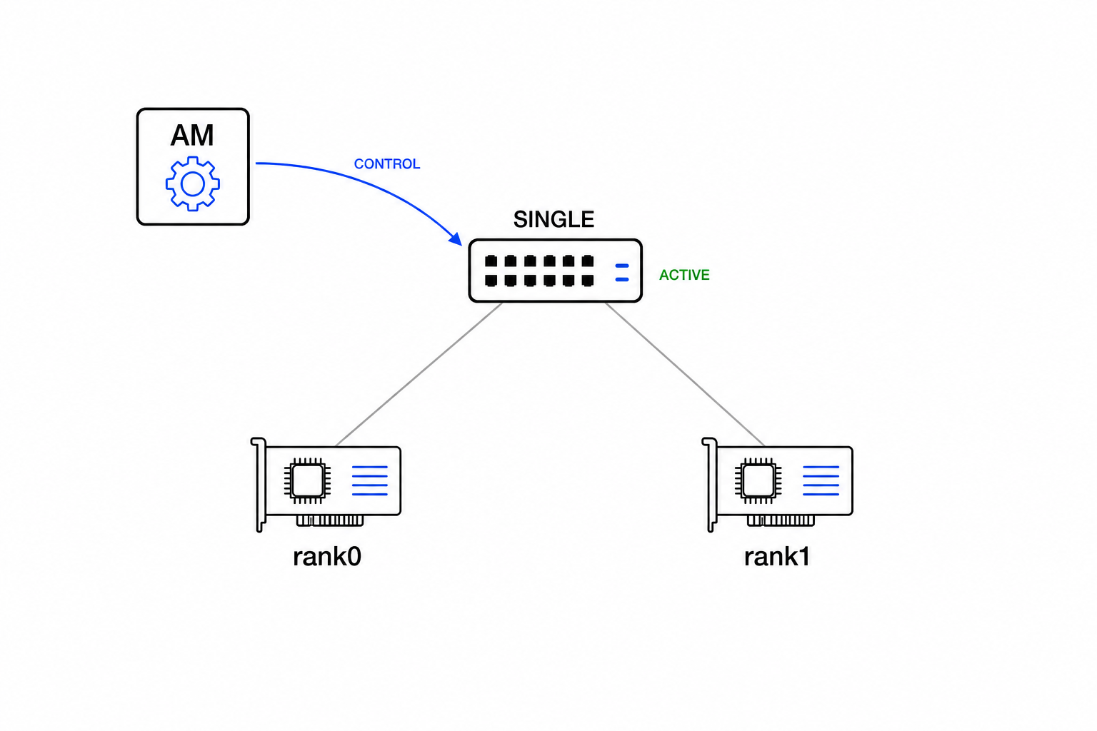
2. Release the endpoints from the barrier
After the SINGLE node reports the operation as ACTIVE, the AM returns a StartGrant to the Host Coordinator. The Coordinator then publishes the two rank-specific grants through the reliable host runtime channel. Only after this step may rank0 and rank1 begin transmitting DATA.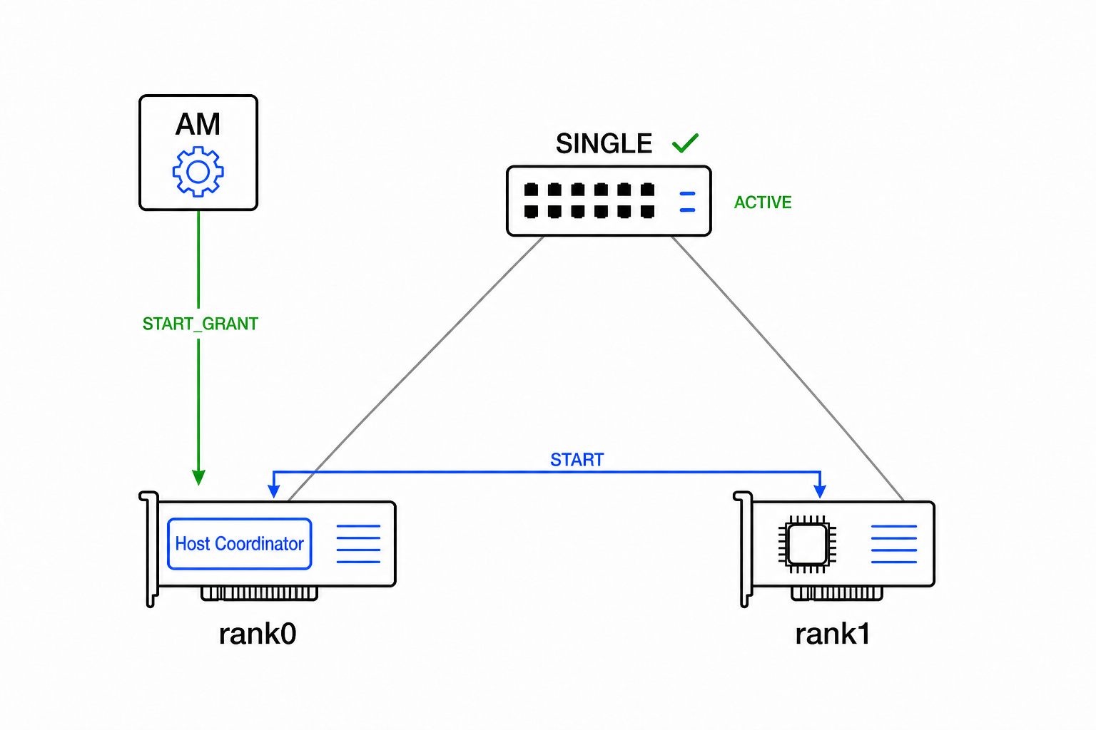
rank0. StartGrant belongs to the host runtime and is not a PRISM opcode or Ethernet packet.
3. Submit endpoint contributions
Each endpoint sends the same logical chunk with its local Contributor ID. The ingress validates identity, source binding, generation, geometry, length, and frame boundary before emitting arithmetic tiles. A duplicate contribution for the same global range is ignored.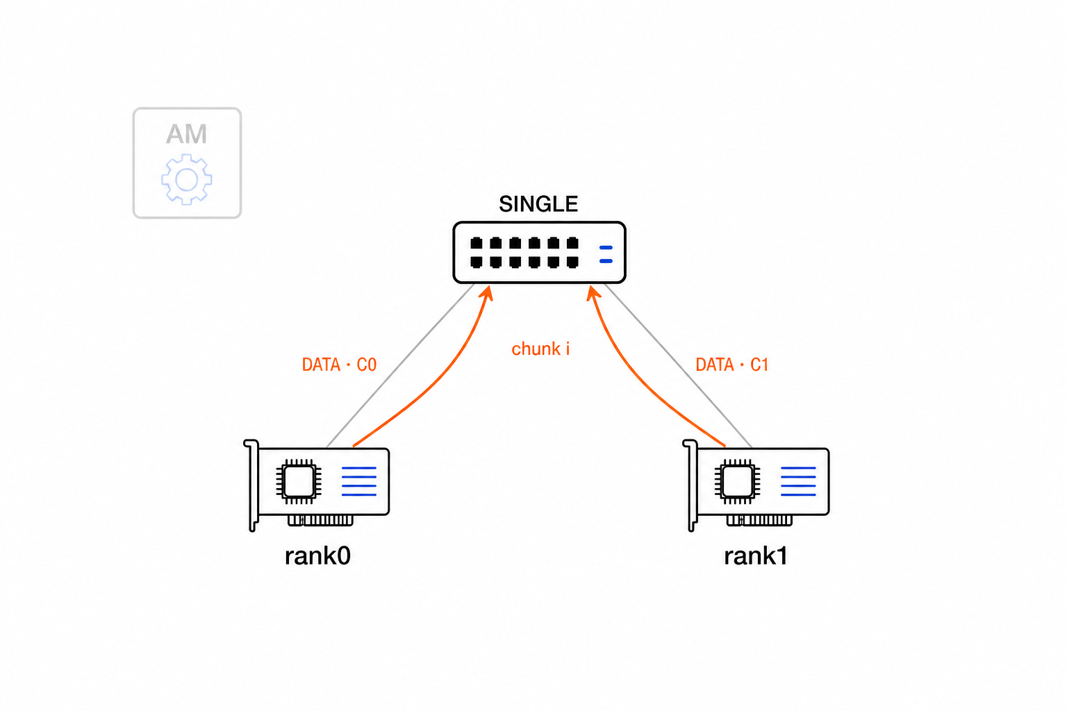
4. Reduce each range
The arithmetic path converts input elements and tracks contributors by global range. Once both contributors arrive, it applies the selected accumulation policy and converts the completed lanes to the output format. Ranges complete independently; a result chunk becomes visible only when all of its tiles are stored.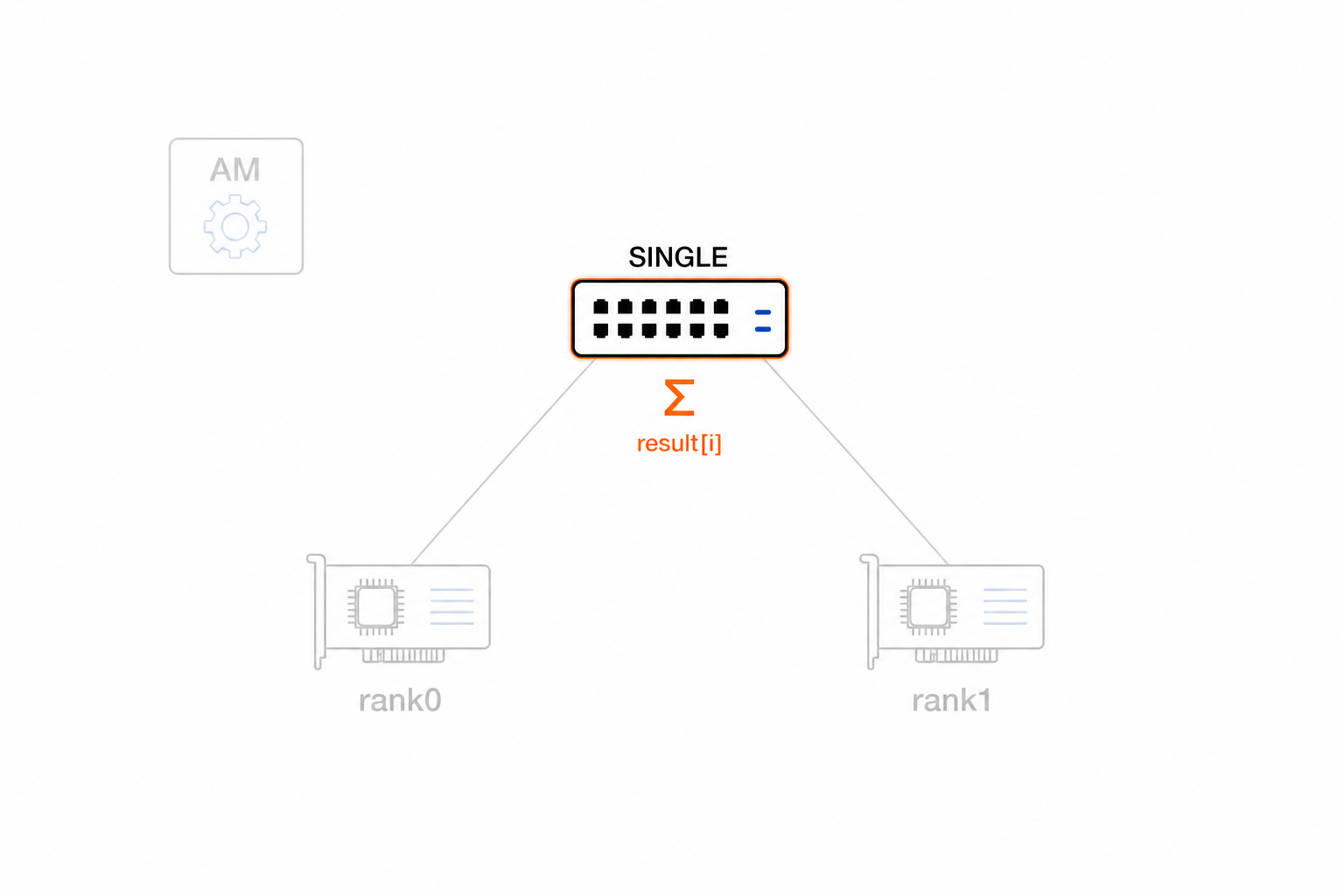
5. Deliver results
For this REDUCE example, the route sends one RES frame to rank1. The packetizer supplies the installed Result Path ID, exact Chunk Index, length, and frame boundary. ALLREDUCE instead creates one packet job per endpoint while retaining the shared result chunk until every replica finishes.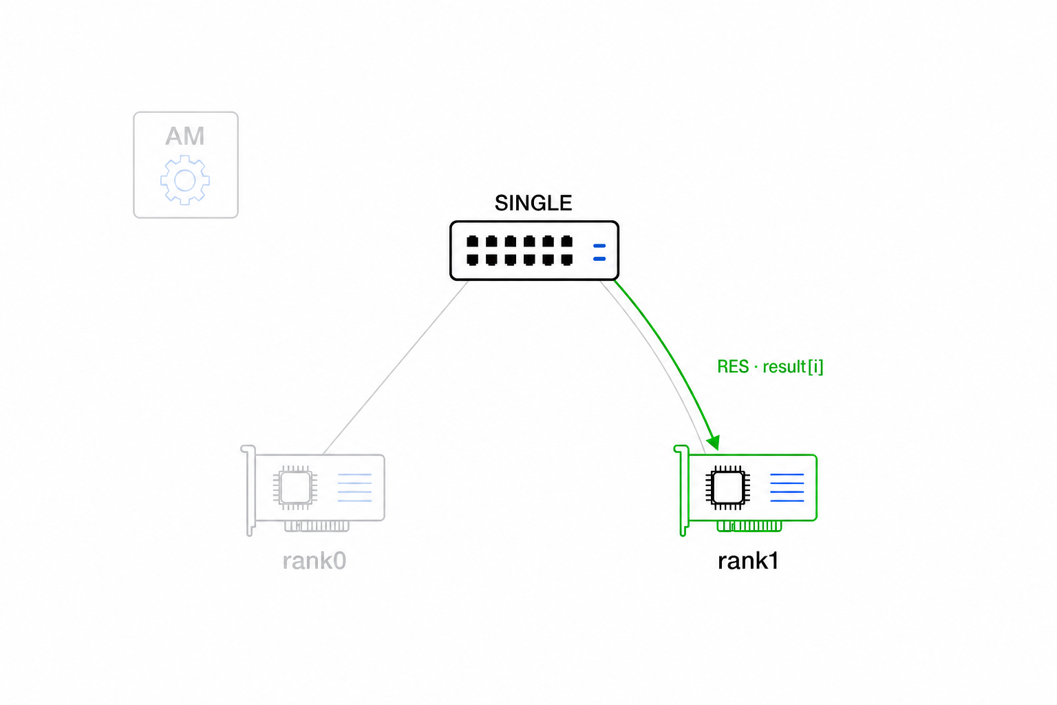
CONTROL responses and RES share each egress through a frame-locking arbiter, so their beats cannot interleave.
The current receive path does not consume switch partial DATA, RES, or PROGRESS frames. Multi-switch aggregation and hop-by-hop retry are described in Future work.
Spine-leaf collective flow
The following storyboard explains the complete protocol design with one spine S0, two leaves L0 and L1, and four ranks. It is the target multi-switch flow. The current RTL implements the SINGLE-node subset described above; switch-to-switch partials and hop-by-hop replay remain future work.
For chunk \(i\):
Steps 1 to 3 start one invocation, steps 4 to 7 can overlap across chunks, and steps 8 to 9 close and release the operation.
1. Ranks request the collective
The ranks enter the same runtime collective. rank0 also hosts the Host Coordinator, which waits for the participant set before asking the Aggregation Manager (AM) to begin. No PRISM DATA packet is sent yet.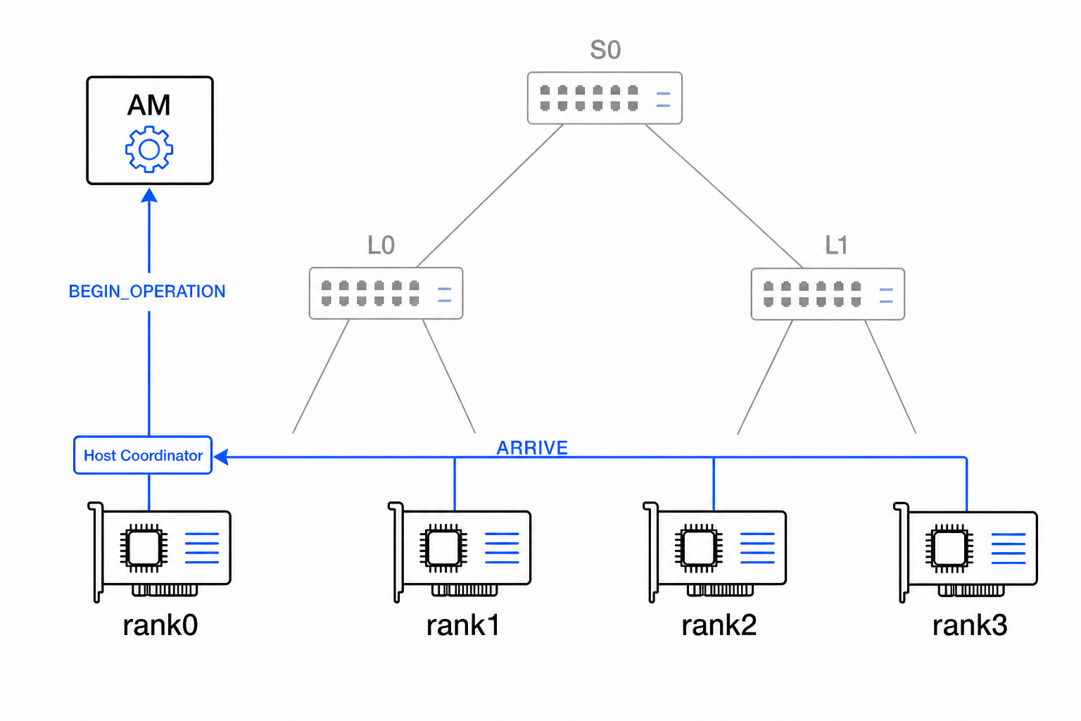
2. Configure the switch tree
The AM installs the reusable Group when needed, then prepares and commits one Operation on each target switch.
| Node | Local reduction | Result direction |
|---|---|---|
L0 | rank0, rank1 to one partial | toward rank1 |
L1 | rank2, rank3 to one partial | none |
S0 | partials from L0, L1 to the final result | toward L0 |
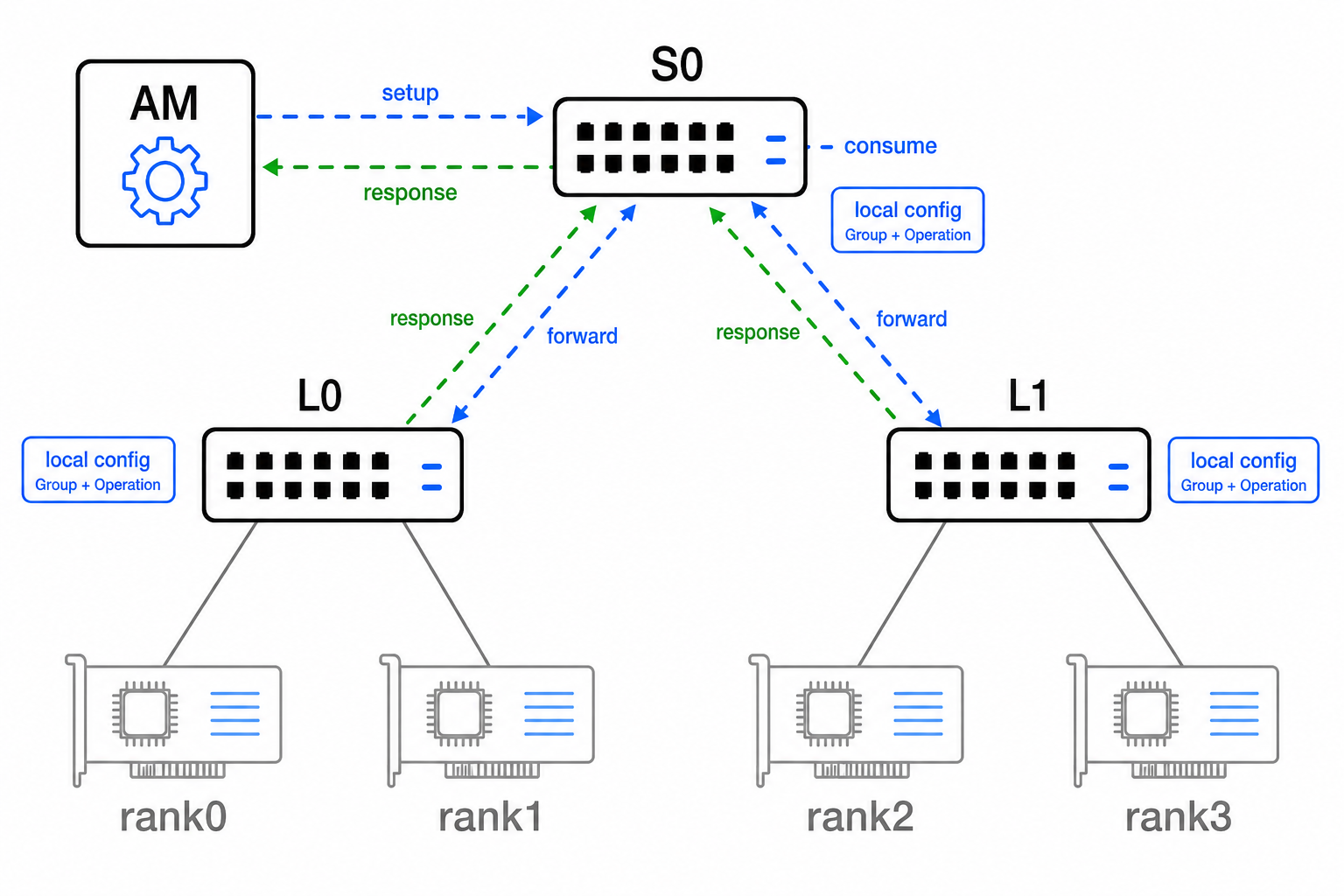
Topology belongs to the Group. Vector length, arithmetic configuration, chunk geometry, and completion state belong to the Operation.
3. Release the ranks from the barrier
The AM returns a StartGrant only after all switches report ACTIVE. The Host Coordinator then publishes rank-specific grants through the runtime. A leaf alone cannot prove that the whole tree is ready.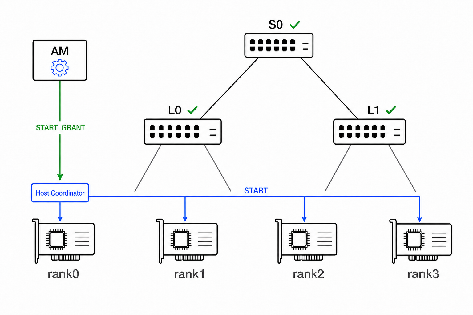
rank0; it is not an additional participant.
4. Submit rank contributions
Each rank sends DATA chunk \(i\) to its configured leaf. The header identifies the Operation, local Contributor ID, and Chunk Index. This example uses FP32 for input, partial, and output, so their chunk geometry is equal. Other format combinations map the same global ranges to different chunk indices.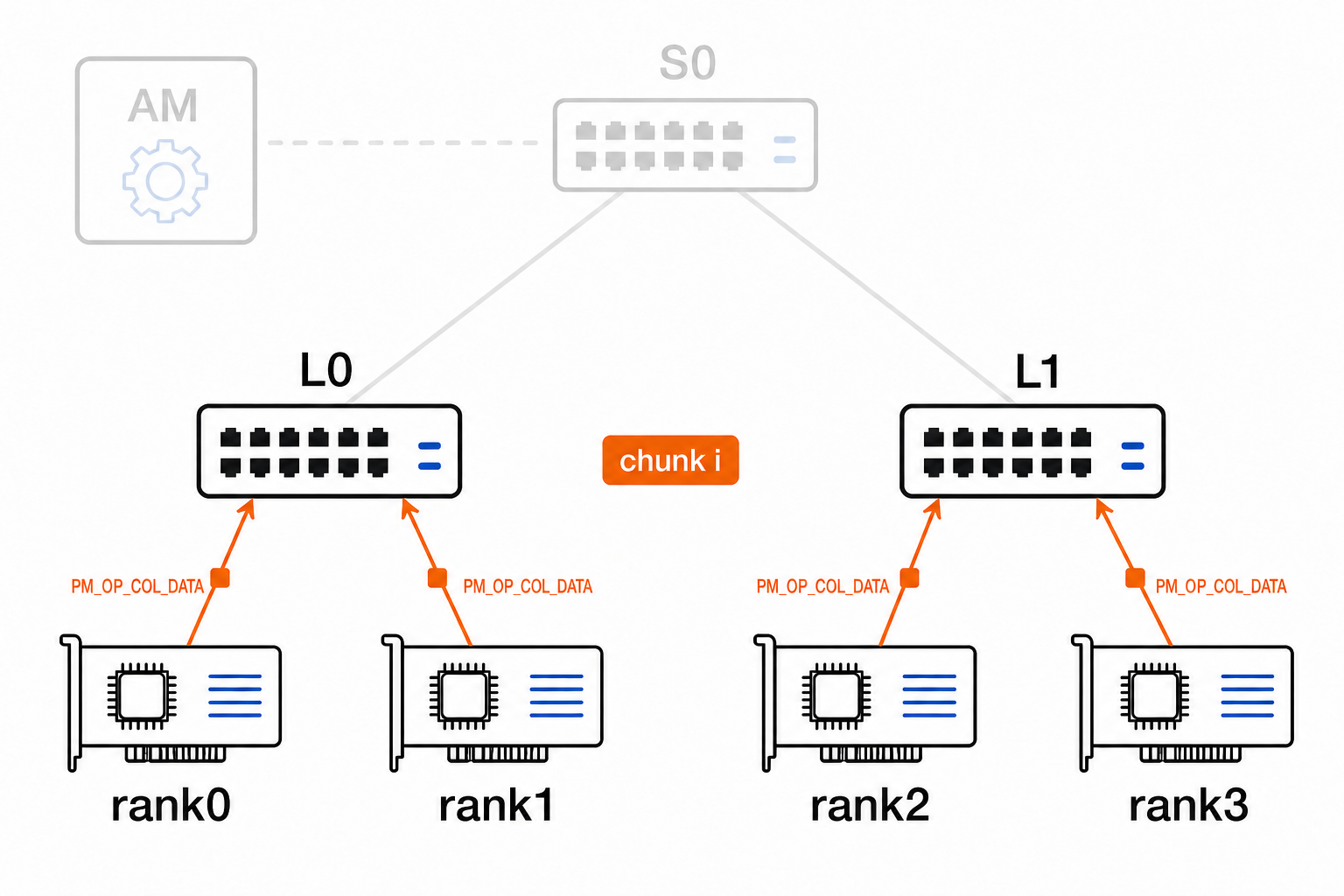
5. Complete the leaf reductions
The leaves reduce independently:
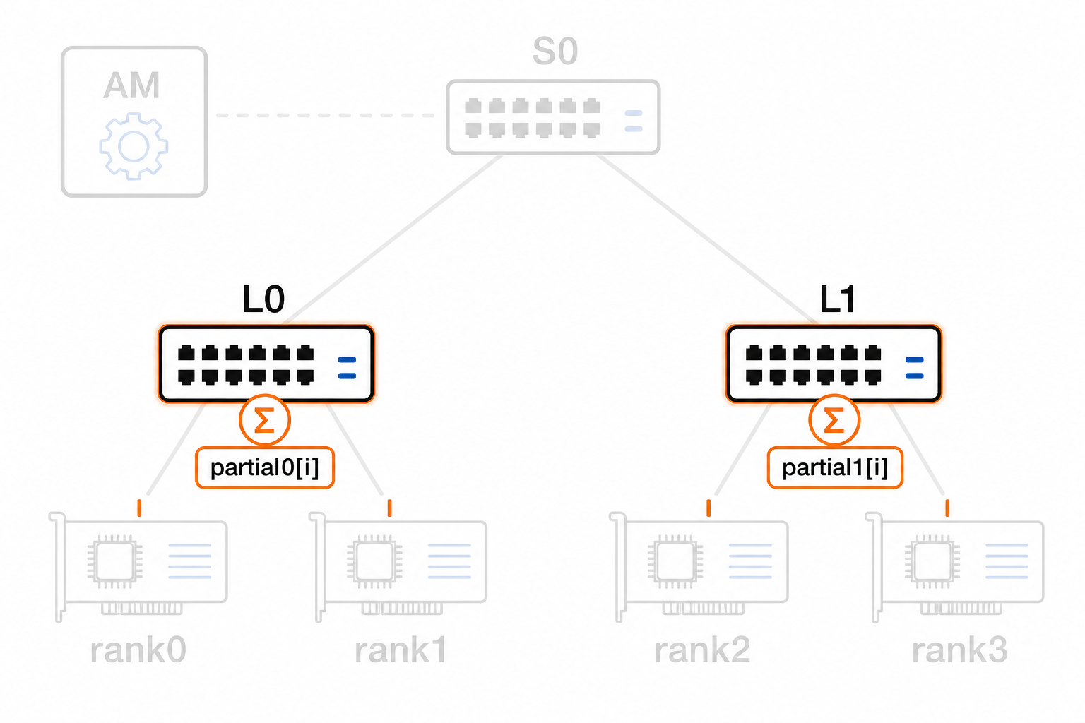
Each leaf retains its completed partial until the parent acknowledges it.
6. Aggregate at the root
The leaves send their partials as DATA. At S0, each child subtree is one local contributor. After both partials arrive:
S0 acknowledges the two direct transfers independently. A leaf may then reuse the replay slot for that partial without waiting for final result delivery.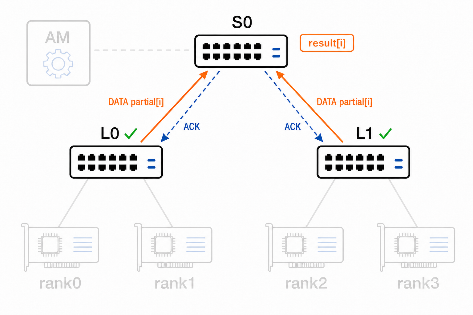
7. Route the result to rank1
The route at S0 sends the result toward L0; the route at L0 selects rank1. Each direct transfer has its own Result Path ID and replay lifetime.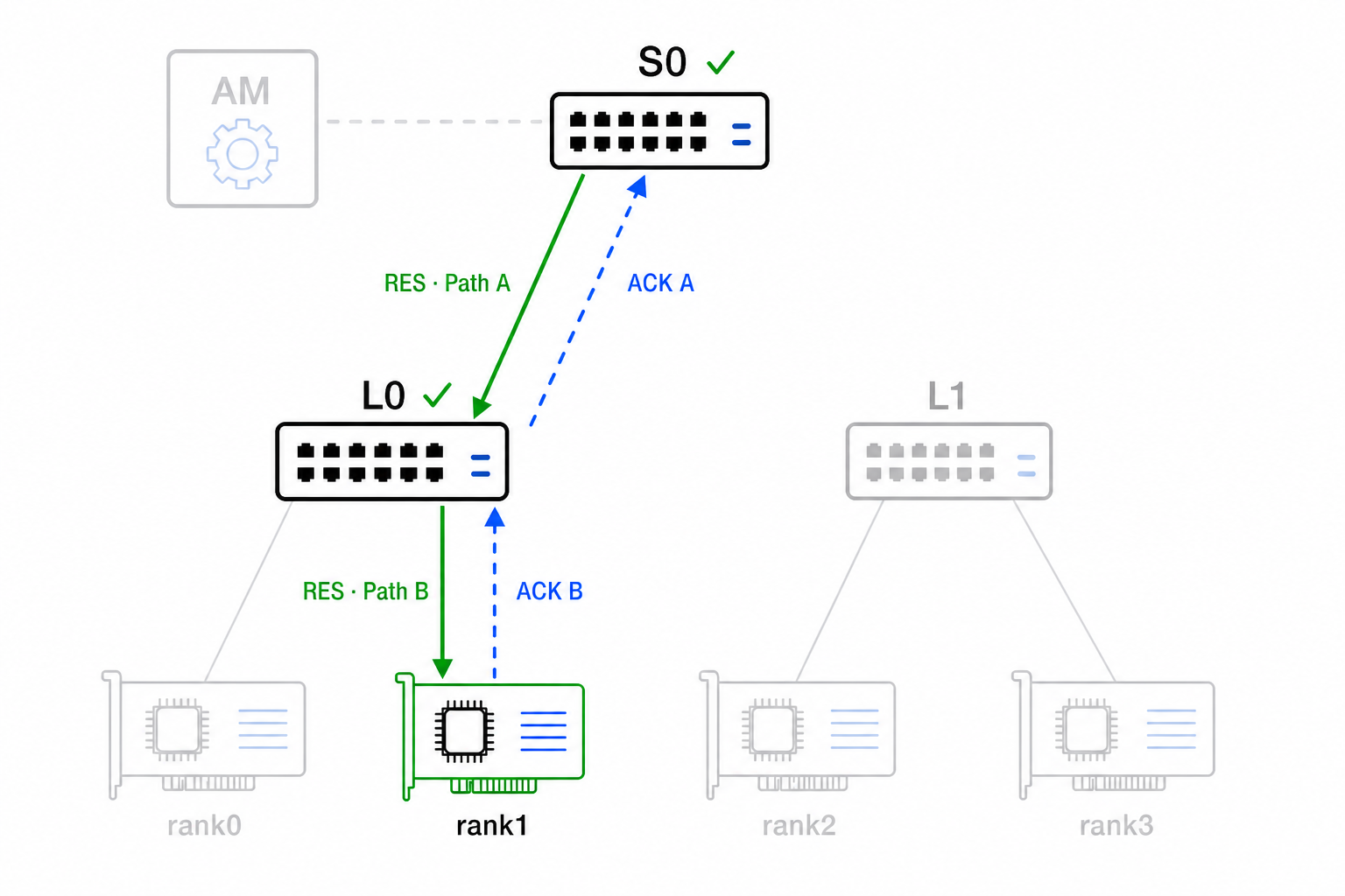
Accepting a result transfers responsibility to the next node. Duplicate packets are acknowledged again but do not update state twice.
8. Complete the operation
Nodes may become COMPLETE at different times. Per-chunk accumulator and replay resources can be reclaimed incrementally, while the Operation handle and retired-generation record remain until release.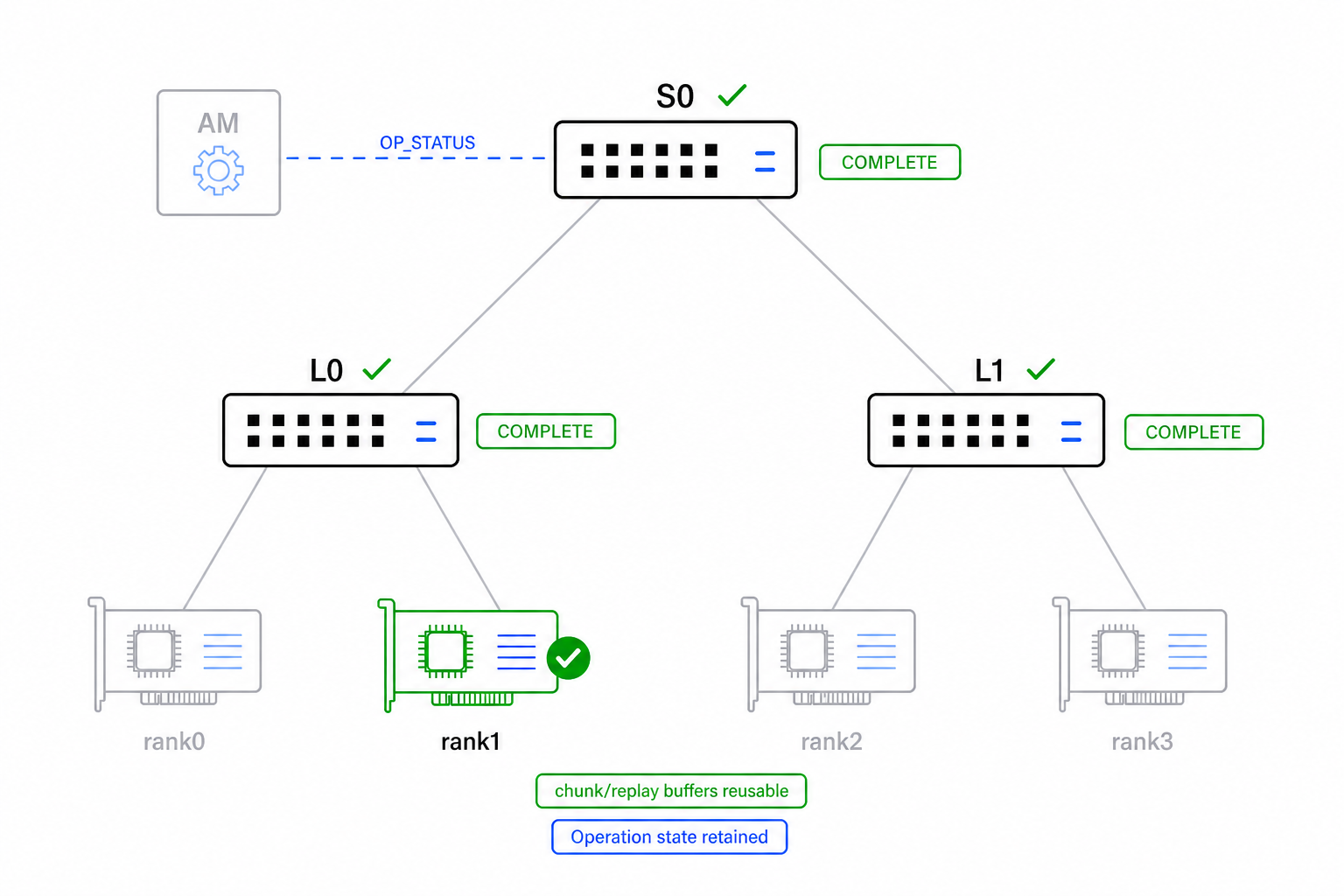
COMPLETE is local status. The AM checks every target before reporting tree-wide completion.
9. Release the Operation state
After tree-wide completion, the Host Coordinator asks the AM to release the Operation on every switch. The reusable Group remains installed.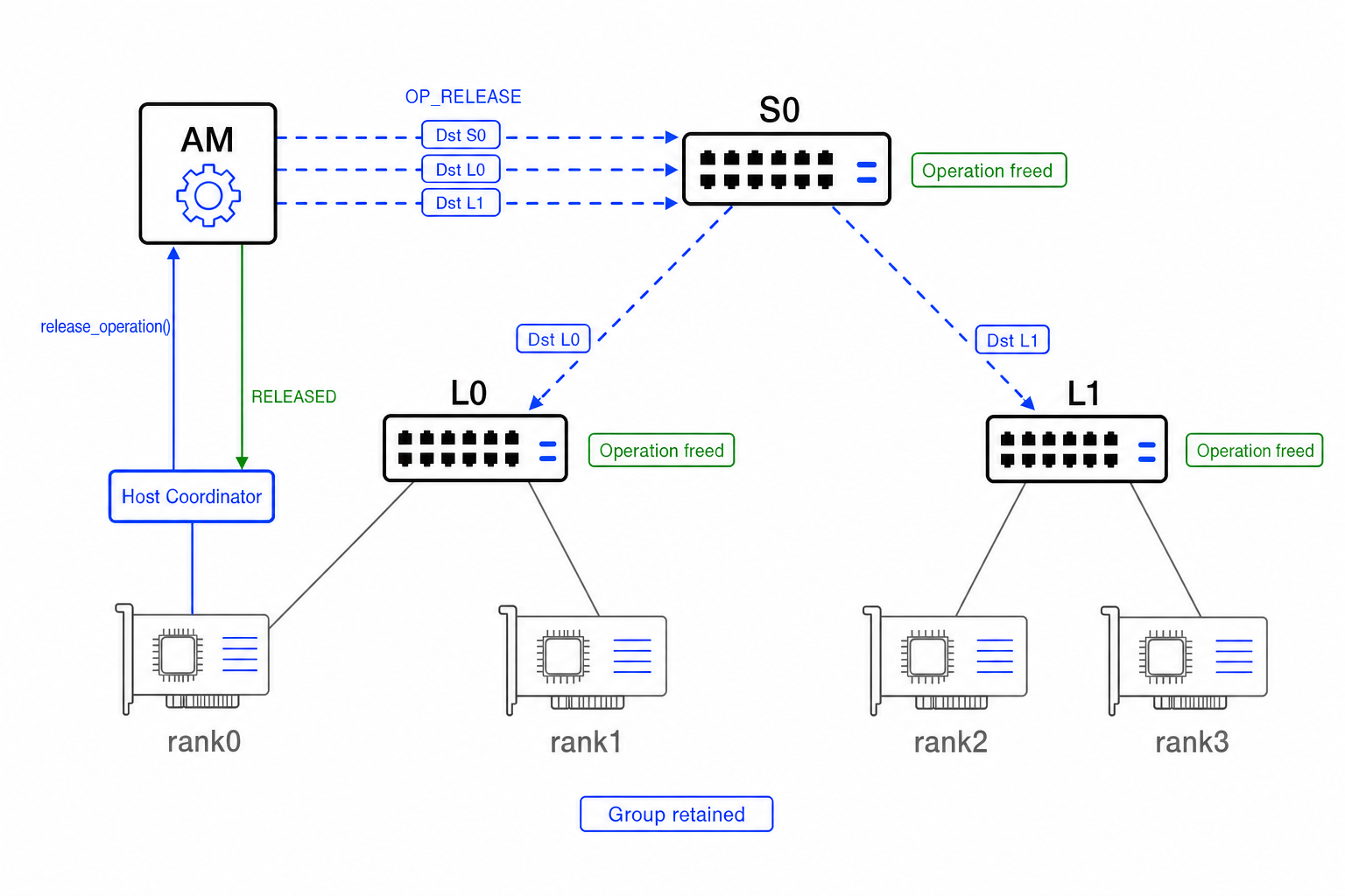
The target lifecycle is:
PREPARED or ACTIVE may enter ABORTED; retained identity state prevents late packets from being accepted as part of a later generation.
How ALLREDUCE differs
Setup and upward aggregation remain the same. Only result delivery changes: S0 replicates toward both leaves and each leaf replicates toward its local participants. Every direct result link retains its own Result Path ID.
Collective semantics
| Value | Semantic | Meaning |
|---|---|---|
0x00 | INVALID | Unsupported collective |
0x01 | REDUCE | Deliver the reduced vector to one selected rank |
0x02 | ALLREDUCE | Deliver the reduced vector to every participating rank |
0x03 | REDUCE_SCATTER | Reserved semantic; support must be advertised |
The current RTL supports REDUCE and ALLREDUCE.
Reduction operator
| Value | Operator | Meaning |
|---|---|---|
0x00 | INVALID | Unsupported operator |
0x01 | SUM | Element-wise addition |
SUM is the reduction operator implemented in the current RTL.
Wire formats and accumulator profiles
An input wire format describes endpoint contributions, a partial wire format describes DATA emitted from one switch to its parent, and an output wire format describes final RES elements. An accumulator profile defines the representation and width of the internal state together with the order in which contributors update it. The four explicit choices keep every conversion boundary selectable and queryable.
| Value | Wire format | Bytes per element |
|---|---|---|
0x01 | INT8 | 1 |
0x02 | FP16 | 2 |
0x03 | BF16 | 2 |
0x04 | FP32 | 4 |
Protocol 1.0 assigns only FP32 for switch-to-switch partials:
| Value | Partial Wire Format | Bytes per element |
|---|---|---|
0x00 | INVALID | Not applicable |
0x04 | FP32 | 4 |
This is deliberately stricter than the endpoint format registry: it prevents a tree from narrowing partials to INT8, FP16, or BF16 at every hop.
The accumulator-profile assignments are:
| Value | Accumulator profile | Meaning |
|---|---|---|
0x00 | INVALID | Unsupported profile |
0x01 | FP32_ARRIVAL | One IEEE 754 binary32 value per element; admissible contributors are applied in arrival order |
0x02 | FP32_ORDERED | One IEEE 754 binary32 value per element; contributors are applied in ascending local Contributor ID order |
0x03 | KULISCH_FP32 | Exact scalar-sum accumulator for input formats up to FP32; state uses the one width configured in the bitstream |
Assignment of a code does not claim RTL support: the complete (input, accumulator profile, partial, output) tuple must be advertised and accepted by OP_PREPARE.
KULISCH_FP32 uses the one accumulator width configured in the bitstream. During admission, a switch derives the exact width required by the Reduction Operator, selected input format, and Maximum Reduction Terms and compares it with that configured width. An insufficient width is reported through the sticky ACCUMULATION_INEXACT status; it does not select another datapath. Protocol 1.0 supports only scalar SUM; a future dot-product operator requires the wider product bound and enough descriptor information for both operands. Protocol 1.0 does not yet assign a lossless Kulisch Partial Wire Format. Using an FP32 partial would still round at every switch boundary, so tree-exact operation additionally requires a compatible partial encoding. See Floating-Point Reproducibility for the numerical derivation.
Normative registries and setup records
The packet path above is sufficient to understand the protocol. The following collapsed blocks are the exact implementation reference for parser, RTL, and host-software work. Control commands The Protocol 1.0 command registry uses three columns to remain readable. The schema cell lists required, optional, and repeatable TLVs; TLV type assignments Group records The 4-byte The 8-byte The repeated Each 12-byte Contributor IDs are exactly the dense range The 16-byte A It is followed by exactly Entry Count 12-byte result-destination entries: Entry Count is positive. Result Path IDs and Operation records The 6-byte The 32-byte Each 8-byte Route ranges lie within the derived output-stream geometry and do not overlap. On a result-delivery node they cover every RES Chunk Index. There is no priority, first-match, or longest-match rule; disjoint ranges may select the same replication group. A resource snapshot reports availability but reserves nothing. Only Capability keys Supported-semantic, operator, format, accumulator-profile, and security-profile values are bitmasks with bit For Dynamic resource keys Reservation, grant, and release keys Status assignments Remaining numeric registries Each name and value below is one canonical Protocol 1.0 assignment. The Security extension bits are outside the Protocol 1.0 baseline. Future accumulator profiles and partial formats use Control commands and TLV registry
; means that the command carries none.Value Command Accepted TLVs 0x0000INVALIDreserved 0x0001CAPS_QUERYOptional: SECURITY_PROFILE0x0002CAPS_RESPONSERequired: DEVICE_BOOT_ID, PROTOCOL_VERSION_RANGE, CAPABILITIES
Optional: FEATURE_MASK, SECURITY_PROFILE0x0003RESOURCE_QUERYOptional: GROUP_HANDLE, OPERATION_HANDLE0x0004RESOURCE_RESPONSERequired: RESOURCE_SNAPSHOT_ID, RESOURCE_SNAPSHOT
Optional: SESSION_USAGE0x0010SESSION_OPENRequired: JOB_ID, SECURITY_PROFILE
Optional: AUTH_DATA, LEASE_MS0x0011SESSION_OPEN_RESPONSERequired: SESSION_COOKIE, DEVICE_BOOT_ID, LEASE_MS, LEASE_GRACE_MS0x0012SESSION_RENEWOptional: LEASE_MS, AUTH_DATA0x0013SESSION_RENEW_RESPONSERequired: LEASE_MS0x0014SESSION_CLOSENot applicable 0x0015SESSION_CLOSE_RESPONSEOptional: RELEASED_RESOURCES0x0100GROUP_STAGERequired: GROUP_HANDLE, GROUP_DESCRIPTOR, UPSTREAM_ACTION
Optional: CONTRIBUTOR_BINDING, REPLICATION_GROUP
Repeatable: CONTRIBUTOR_BINDING, REPLICATION_GROUP0x0101GROUP_STAGE_RESPONSERequired: GROUP_HANDLE, RESOURCE_RESERVATION0x0102GROUP_COMMITRequired: GROUP_HANDLE0x0103GROUP_COMMIT_RESPONSERequired: GROUP_HANDLE, GROUP_STATUS0x0104GROUP_ABORTRequired: GROUP_HANDLE0x0105GROUP_ABORT_RESPONSEOptional: RELEASED_RESOURCES0x0106GROUP_STATUSRequired: GROUP_HANDLE0x0107GROUP_STATUS_RESPONSERequired: GROUP_HANDLE, GROUP_STATUS0x0108GROUP_DESTROYRequired: GROUP_HANDLE0x0109GROUP_DESTROY_RESPONSERequired: GROUP_HANDLE
Optional: RELEASED_RESOURCES0x0200OP_PREPARERequired: GROUP_HANDLE, OPERATION_HANDLE, OPERATION_DESCRIPTOR
Optional: RESULT_ROUTE_RANGE, RETRY_POLICY
Repeatable: RESULT_ROUTE_RANGE0x0201OP_PREPARE_RESPONSERequired: OPERATION_HANDLE, GRANTED_RESOURCES0x0202OP_COMMITRequired: OPERATION_HANDLE0x0203OP_COMMIT_RESPONSERequired: OPERATION_HANDLE, OPERATION_STATUS0x0204OP_ABORTRequired: OPERATION_HANDLE0x0205OP_ABORT_RESPONSERequired: OPERATION_HANDLE, OPERATION_STATUS0x0206OP_STATUSRequired: OPERATION_HANDLE0x0207OP_STATUS_RESPONSERequired: OPERATION_HANDLE, OPERATION_STATUS
Optional: PHASE_BITMAP_SUMMARY, ERROR_DETAIL0x0208OP_RELEASERequired: OPERATION_HANDLE0x0209OP_RELEASE_RESPONSERequired: OPERATION_HANDLE
Optional: RELEASED_RESOURCES0x0300OP_COMPLETE_EVENTRequired: OPERATION_HANDLE, EVENT_DETAIL0x0301OP_ERROR_EVENTRequired: OPERATION_HANDLE, EVENT_DETAIL, ERROR_DETAIL0x0302RESOURCE_PRESSURE_EVENTRequired: EVENT_DETAIL0x0303EVENT_ACKRequired: EVENT_DETAILValue TLV type Family 0x0000INVALIDGeneral 0x0001JOB_IDGeneral 0x0002DEVICE_BOOT_IDGeneral 0x0003SESSION_COOKIEGeneral 0x0004LEASE_MSGeneral 0x0005LEASE_GRACE_MSGeneral 0x0006SECURITY_PROFILEGeneral 0x0007FEATURE_MASKGeneral 0x0008PROTOCOL_VERSION_RANGEGeneral 0x0009CAPABILITIESGeneral 0x000ARESOURCE_SNAPSHOT_IDGeneral 0x000BRESOURCE_SNAPSHOTGeneral 0x000CRESOURCE_RESERVATIONGeneral 0x000DPAYLOAD_DIGESTGeneral 0x000EERROR_DETAILGeneral 0x000FRELEASED_RESOURCESGeneral 0x0010AUTH_DATAGeneral 0x0011SESSION_USAGEGeneral 0x0100GROUP_HANDLEGroup 0x0101GROUP_DESCRIPTORGroup 0x0102CONTRIBUTOR_BINDINGGroup 0x0103UPSTREAM_ACTIONGroup 0x0104REPLICATION_GROUPGroup 0x0105GROUP_STATUSGroup 0x0200OPERATION_HANDLEOperation 0x0201OPERATION_DESCRIPTOROperation 0x0202RESULT_ROUTE_RANGEOperation 0x0203GRANTED_RESOURCESOperation 0x0204OPERATION_STATUSOperation 0x0205PHASE_BITMAP_SUMMARYOperation 0x0206RETRY_POLICYOperation 0x0300EVENT_DETAILEvent CONTRIBUTOR_BINDING, REPLICATION_GROUP, and RESULT_ROUTE_RANGE are repeatable only in commands whose schema permits repetition.Group and operation record layouts
GROUP_HANDLE value is:Offset Width Field 0 16 Group ID 2 16 Group Generation GROUP_DESCRIPTOR value is:Offset Width Field 0 8 Node Role 1 8 Flags, zero in Protocol 1.0 2 16 Expected Local Contributors 4 32 Reserved, zero REPLICATION_GROUP records declare the exact replication groups and result destinations installed for this group. Staging reserves those actual records, subject to the switch's compiled capability limits. A committed group is immutable: changing its contributors, upstream action, or replication data requires GROUP_DESTROY followed by a new GROUP_STAGE/GROUP_COMMIT using a new generation.CONTRIBUTOR_BINDING value is:Offset Width Field 0 16 Contributor ID 2 16 Ingress Port 4 48 Source MAC 10 16 Reserved, zero 0 <= id < expected_local_contributors. Contributor IDs and (Ingress Port, Source MAC) bindings are unique.UPSTREAM_ACTION value is:Offset Width Field 0 8 Has Parent, 0 or 11 8 Reserved, zero 2 16 Parent Contributor ID 4 16 Egress Port 6 48 Parent MAC 12 32 Reserved, zero REPLICATION_GROUP begins with an 8-byte header:Offset Width Field 0 16 Replication Group ID 2 16 Entry Count 4 32 Reserved, zero Entry offset Width Field 0 16 Result Path ID 2 16 Egress Port 4 8 Next-Hop Type 5 8 Reserved, zero 6 48 Destination MAC (Egress Port, Destination MAC) pairs are unique within the replication group.OPERATION_HANDLE value is:Offset Width Field 0 16 Operation ID 2 32 Operation Generation OPERATION_DESCRIPTOR value is:Offset Width Field 0 8 Collective Semantic 1 8 Reduction Operator 2 8 Input Wire Format 3 8 Accumulator Profile 4 8 Partial Wire Format 5 8 Output Wire Format 6 8 Flags; bit 0 is Result Delivery Role, all other bits zero 7 8 Reserved, zero 8 32 Element Count 12 32 Maximum Reduction Terms 16 32 Timeout, ms 20 16 Requested Window, in direct-stream chunks 22 16 Requested Replay Slots 24 16 Result-Range Route Count 26 16 Retry Limit 28 32 Reserved, zero Elements per Chunk and Expected Chunks are deliberately absent. Every node derives the input, partial, and output geometries from Element Count, the corresponding advertised wire format, and the negotiated Maximum PRISM Payload Bytes. A descriptor is rejected if any resulting chunk count exceeds the 24-bit Chunk Index space. Removing duplicate geometry eliminates disagreement between control state and packet validation.RESULT_ROUTE_RANGE value is:Offset Width Field 0 24 First Output Wire Format RES Chunk Index, inclusive 3 24 Last Output Wire Format RES Chunk Index, inclusive 6 16 Replication Group ID Capability, resource, and allocation vectors
CAPABILITIES, RESOURCE_SNAPSHOT, SESSION_USAGE, RESOURCE_RESERVATION, GRANTED_RESOURCES, and RELEASED_RESOURCES use 16-byte entries:Offset Width Field 0 16 Key 2 16 Flags, zero 4 64 Value 12 32 Reserved, zero GROUP_STAGE and OP_PREPARE reserve resources.Value Capability key 0x0000INVALID0x0001MAX_SESSIONS0x0002MAX_INSTALLED_GROUPS0x0003MAX_OPERATION_CONTEXTS0x0004MAX_ACTIVE_OPERATIONS_GLOBAL0x0005MAX_ACTIVE_OPERATIONS_PER_GROUP0x0006MAX_CHUNKS_PER_DIRECT_STREAM0x0007MAX_BITMAP_BYTES_PER_OPERATION0x0008TOTAL_PHASE_BITMAP_POOL_BYTES0x0009MAX_ACTIVE_ACCUMULATOR_RANGES_GLOBAL0x000AMAX_ACTIVE_ACCUMULATOR_RANGES_PER_OPERATION0x000BTOTAL_REPLAY_OUTPUT_SLOTS0x000CMAX_LOCAL_CONTRIBUTORS0x000DMAX_REPLICATION_GROUPS0x000EMAX_RESULT_DESTINATIONS_PER_GROUP0x000FMAX_OPERATION_RESULT_ROUTE_RANGES0x0010MAX_MANAGEMENT_STAGING_BYTES0x0011MAX_SELECTIVE_ACK_WINDOW0x0012SUPPORTED_COLLECTIVE_SEMANTICS0x0013SUPPORTED_REDUCTION_OPERATORS0x0014SUPPORTED_INPUT_FORMATS0x0015SUPPORTED_ACCUMULATOR_PROFILES0x0016SUPPORTED_PARTIAL_FORMATS0x0017SUPPORTED_OUTPUT_FORMATS0x0018MTU_BYTES0x0019MAX_PRISM_PAYLOAD_BYTES0x001ASUPPORTED_SECURITY_PROFILES0x001BSUPPORTED_RELIABILITY_FEATURES0x001CREPLAY_CACHE_DEPTH0x001DREPLAY_CACHE_RETENTION_MS0x001EACCUMULATOR_PROFILE_CAPABILITYn corresponding to numeric registry value n. The Protocol 1.0 baseline advertises only security-profile bit 0, LAB_UNAUTHENTICATED. The input, accumulator, partial, and output masks advertise independent sets; their Cartesian product is supported. This compact representation grows with the number of values rather than with the number of combinations. An implementation with a non-Cartesian arithmetic restriction must not advertise the restricted values together in Protocol 1.0.ACCUMULATOR_PROFILE_CAPABILITY entries encode profile ID in bits 63:56, accumulator state bits per element in 55:40, maximum supported reduction terms in 39:8, and profile flags in 7:0. Profile flag bit 0 means that the profile can be carried as a Partial Wire Format when a compatible arithmetic record is advertised; other bits are zero in Protocol 1.0. This key appears exactly once for each advertised accumulator profile; all other capability keys appear once.KULISCH_FP32, the record advertises the single configured state width and term limit. Given the Reduction Operator, input format, and Maximum Reduction Terms, admission checks that record against the applicable exact-arithmetic bound. An insufficient configuration is admitted with the sticky ACCUMULATION_INEXACT status, and arithmetic continues in the advertised state width.Value Resource key 0x0000INVALID0x0001FREE_GROUP_SLOTS0x0002FREE_OPERATION_CONTEXTS0x0003FREE_ACTIVE_OPERATION_SLOTS0x0004FREE_PHASE_BITMAP_BYTES0x0005FREE_ACCUMULATOR_RANGES0x0006FREE_REPLAY_OUTPUT_SLOTS0x0007FREE_ROUTE_ENTRIES0x0008FREE_REPLICATION_GROUPS0x0009FREE_REPLICATION_ENTRIES0x000ASESSION_GROUP_USAGE0x000BSESSION_PREPARED_OPERATION_USAGE0x000CSESSION_ACTIVE_OPERATION_USAGE0x000DSESSION_BITMAP_USAGE_BYTES0x000ESESSION_ACCUMULATOR_RANGE_USAGEValue Allocation key 0x0000INVALID0x0001GROUP_SLOTS0x0002OPERATION_SLOTS0x0003PHASE_BITMAP_BYTES0x0004ACCUMULATOR_RANGES0x0005REPLAY_OUTPUT_SLOTS0x0006ROUTE_ENTRIES0x0007REPLICATION_GROUPS0x0008REPLICATION_ENTRIESStatus and remaining numeric registries
Value Status 0x00OK0x01UNSUPPORTED_VERSION0x02UNSUPPORTED_COMMAND0x03UNSUPPORTED_FEATURE0x04INVALID_REQUEST0x05INVALID_RECORD0x06INVALID_STATE0x07AUTH_REQUIRED0x08AUTH_FAILED0x09STALE_SESSION0x0ASTALE_DEVICE_BOOT_ID0x0BTXN_CONFLICT0x0CNOT_FOUND0x0DALREADY_EXISTS0x0EGENERATION_MISMATCH0x0FGROUP_BUSY0x10OPERATION_BUSY0x11NO_GROUP_SLOT0x12NO_OPERATION_SLOT0x13NO_BITMAP_MEMORY0x14NO_ACCUMULATOR_RANGE0x15NO_REPLAY_BUFFER0x16NO_ROUTE_RESOURCE0x17NO_REPLICATION_RESOURCE0x18UNSUPPORTED_ARITHMETIC_CONFIGURATION0x19BAD_PAYLOAD_LENGTH0x1AOUT_OF_WINDOW0x1BRETRY0x1CTIMEOUT0x1DABORTED0x1EINTERNAL_ERRORRegistry Assignments Session state CLOSED=0x00, OPEN=0x01, EXPIRING=0x02, ORPHANED=0x03Group state FREE=0x00, STAGED=0x01, INSTALLED=0x02, DESTROYING=0x03Operation state FREE=0x00, PREPARED=0x01, ACTIVE=0x02, COMPLETE=0x03, RELEASING=0x04, ABORTED=0x05Accumulator Range state EMPTY=0x00, ACTIVE=0x01, OUTPUT_PENDING=0x02Node role INVALID=0x00, LEAF=0x01, INTERNAL=0x02, ROOT=0x03, SINGLE=0x04Next-hop type INVALID=0x00, SWITCH=0x01, RANK=0x02Progress peer kind INVALID=0x00, CONTRIBUTOR=0x01, RESULT_PATH=0x02, ENDPOINT=0x03Progress reason NONE=0x00, ACCEPTED=0x01, DUPLICATE=0x02, OUT_OF_WINDOW=0x03, NO_SLOT=0x04, STALE_GENERATION=0x05, BAD_PAYLOAD=0x06, RETRY_LATER=0x07, FATAL_OPERATION=0x08FEATURE_MASK and SUPPORTED_RELIABILITY_FEATURES bits relevant to Protocol 1.0 are:Value Feature bit 0x0001RELIABLE_HOP_BY_HOP0x0002SELECTIVE_ACK0x0004RESULT_ACK0x0008LEASED_SESSIONS0x0010MANAGEMENT_AUTH0x0020MACSEC_MANAGEMENT_DOMAIN0x0040EXTERNAL_BITMAP_MEMORYACCUMULATOR_PROFILE_CAPABILITY and the supported-format masks rather than independent feature bits.
Arithmetic support boundary
Wire-format and accumulator values are registry assignments, not support claims. INT8 payload elements are signed two's-complement bytes; FP16 and FP32 carry IEEE 754 binary16 and binary32 bit patterns; BF16 carries one sign bit, eight exponent bits, and seven fraction bits.
A node supports an arithmetic configuration when each selected input format, accumulator profile, partial format, and output format is present in its corresponding capability mask. OP_PREPARE selects one configuration and the AM requires the same configuration at every switch in the tree. Protocol 1.0 freezes one baseline configuration for the SUM operator:
An implementation advertising this configuration obeys the following normative semantics:
- each input and output is an IEEE 754
binary32bit pattern; - the
FP32_ORDEREDaccumulator profile folds contributors in strictly ascending local Contributor ID order, starting with the value from the lowest ID; no zero seed is inserted; - every binary addition is performed in
binary32and rounded immediately using round-to-nearest, ties-to-even; fused or wider intermediate arithmetic is not permitted; - subnormal inputs and results use gradual underflow and are not flushed to zero;
- finite overflow produces the correctly signed infinity;
- infinity follows IEEE 754 addition, including an invalid
+infinity +
  -infinity
result; - any NaN input, signaling NaN, or invalid addition produces the canonical quiet NaN bit pattern
0x7FC00000; no NaN payload is propagated; - same-sign zero addition preserves that sign; an exact zero sum of opposite signs is
+0under the selected rounding mode; - arithmetic exception flags and traps are not transported by Protocol 1.0.
RFC 9542 reserves
0x88B5and0x88B6for local experimental use. They are appropriate for this research prototype, not a globally assigned production protocol. https://www.rfc-editor.org/rfc/rfc9542.html ↩